2-59
Intake and exhaust system
Intake and exhaust system
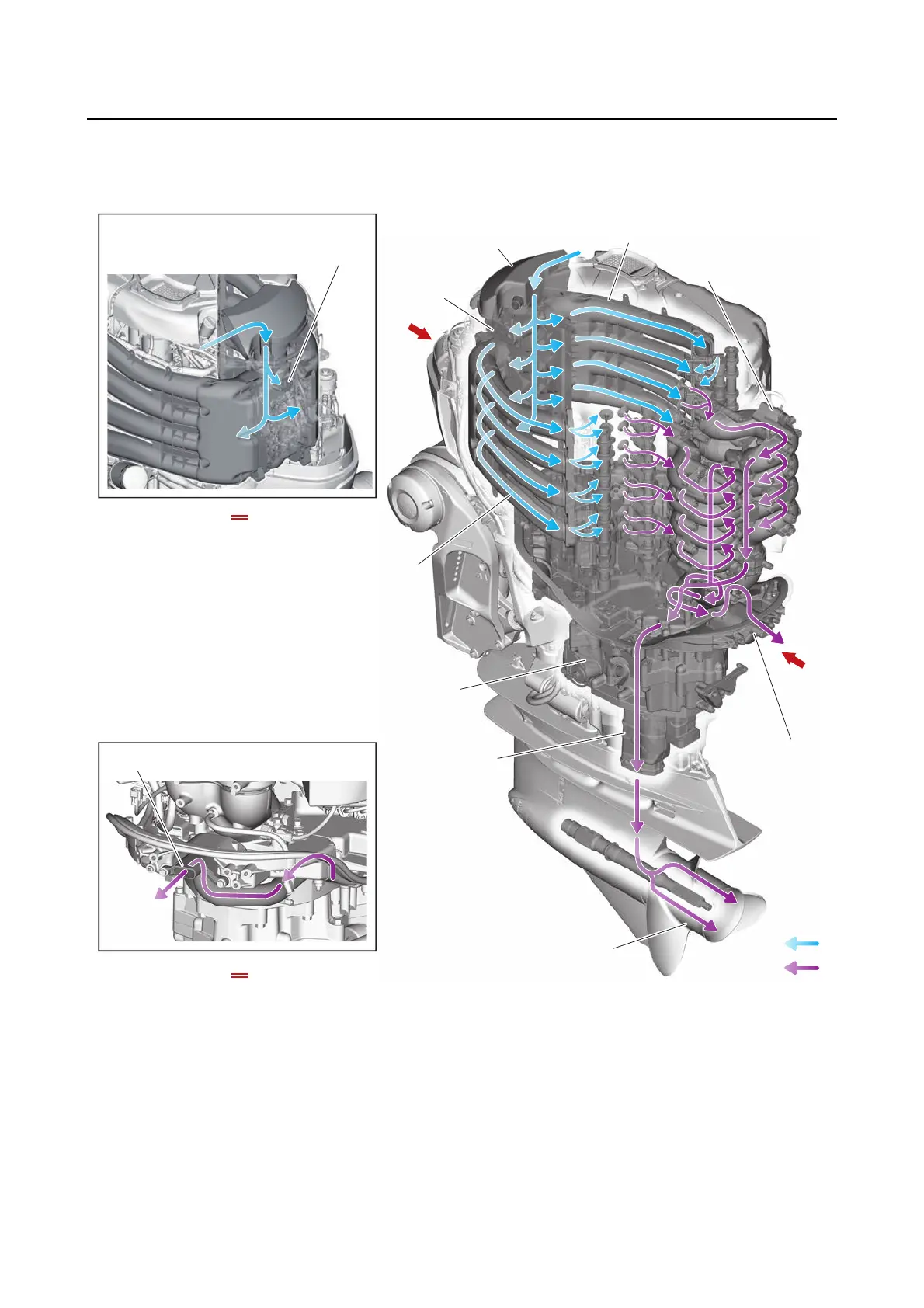
Intake and exhaust diagram
A
B
3. Intake air pressure/
temperature sensor
10. Idle exhaust hole
4. Intake manifold (PORT)
1. Intake silencer
2. ETV
7. Oil pan
9. Propeller boss
10. Idle exhaust
hole
10. Idle exhaust
hole
6. Exhaust joint
5. Intake manifold (STBD)
8. Muffler
A
B
A
B
1. Intake silencer
2. ETV
3. Intake air pressure/temperature sensor
4. Intake manifold (PORT)
5. Intake manifold (STBD)
6. Exhaust joint
7. Oil pan
8. Muffler
9. Propeller boss
10. Idle exhaust hole
A. Intake air flow
B. Exhaust gas flow