9-40
Steering actuator and steering arm
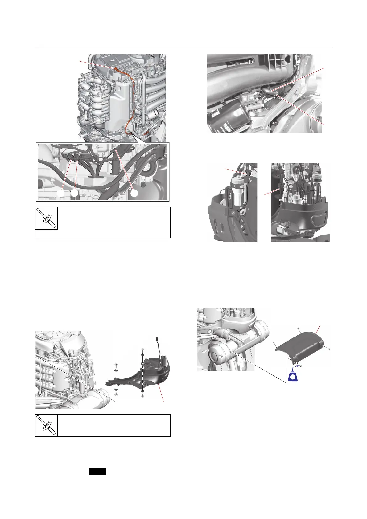
3. Install:
• Protector cover
• SCU lead
(to the holders)
See step 5 in “Installing the upper case
assembly” (9-21).
• Dipstick guide
See “Intake manifold” (6-24).
4. Install:
• Bottom cowling (front) “1”
5. Connect:
• Flushing hose “1”
(to the joint)
• Plastic tie “2”
6. Connect:
• PTT switch coupler “a”
• Main wire harness coupler “b”
7. Install:
• Rigging grommet
• Grommet holder
•Plastic tie
See “Rigging grommet mounting” (3-13).
8. Install:
• Swivel bracket top cover “1”
9. Install:
• Low-pressure fuel pump bracket bolts “1”
•Cover “2”
Electrical management box termi-
nal nut
7.6 N·m (0.76 kgf·m, 5.6 lb·ft)
Bottom cowling (front) bolt
19 N·m (1.9 kgf·m, 14 lb·ft)