7-32
Wire harness
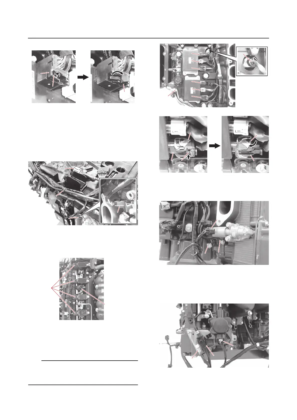
6. Disconnect:
• Wire harness “a”
(from the guide)
• Cam position sensor coupler (PORT IN)
“b”
• Joint connector “c”
(from the guide)
7. Disconnect:
• Ignition coil coupler (PORT) “a”
• Fuel pressure sensor (direct injection
pump) coupler (PORT) “b”
8. Disconnect:
• Engine temperature sensor coupler “a”
• Injector driver coupler “b”, “c”, “d”
• PTT buzzer coupler “e”
While pushing the tab “f” of the injector driver
coupler “d”, move the lock lever “g” in the di-
rection shown to disengage the coupler.
9. Disconnect:
• Ground lead “a”, “b”
• OCV coupler (PORT) “c”
10. Disconnect:
• PTT sensor coupler “a”
(from the bracket)
• Sub-wire harness coupler (PORT) “b”
• Direct injection pump coupler (PORT) “c”
11. Disconnect:
• Cam position sensor coupler (PORT EX)
“a”