7-2
Power unit (check and adjustment)
Do not turn the flywheel magneto counter-
clockwise. Otherwise, the water pump im-
peller could be damaged.
1. Reduce:
•Fuel pressure
See “Reducing the fuel pressure” (6-1).
2. Remove:
• Bottom cowling cover
See “Bottom cowling cover and apron
cover” (9-1).
• Bottom cowling
See “Bottom cowling (PORT and STBD)”
(9-3).
• Shroud cover and terminal cover
See “Shroud cover and terminal cover”
(7-5).
• Electrical management box
See “Electrical management box” (7-22).
• Fuel rail cover
See “Fuel hose assembly” (6-12).
• Exhaust joint
See “Exhaust joint (outside)” (7-7) and
“Exhaust joint (inside)” (7-11).
• Ignition coil
• Spark plug
See “Ignition coil and spark plug” (7-40).
• Fuel hose
(from the direct injection pump)
• Fuel rail
See “Direct injection pump and fuel injec-
tor” (6-18).
• Wire harness guide
See “Timing belt” (7-42).
• Cylinder head cover
See “Camshaft” (7-46).
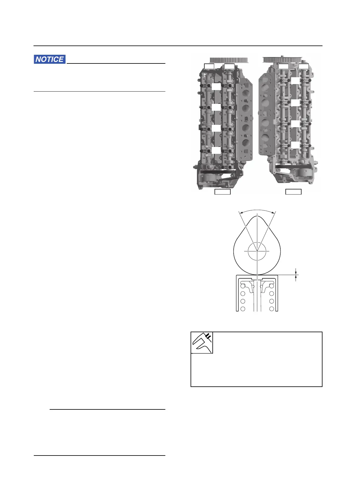
3. Measure:
• Valve clearance “a”
Out of specification → Adjust.
See “Adjusting the valve clearance” (7-3).
• Turn the crankshaft gradually until the cam
nose for each valve is positioned within the
range “b”, and then measure the valve clear-
ance for that valve.
• Write down the measurement data.
4. Install:
• Cylinder head cover
See “Camshaft” (7-46).
• Wire harness guide
See “Timing belt” (7-42).
•Fuel rail
• Fuel hose
(from the direct injection pump)
b. 60°
Valve clearance IN (cold engine)
0.17–0.24 mm (0.0067–0.0094
in)
Valve clearance EX (cold engine)
0.37–0.44 mm (0.0146–0.0173
in)
#1
#3
#5
#7
#2
#4
#6
#8
PORT
STBD
EX
IN
EX
IN