7-84
Cylinder block
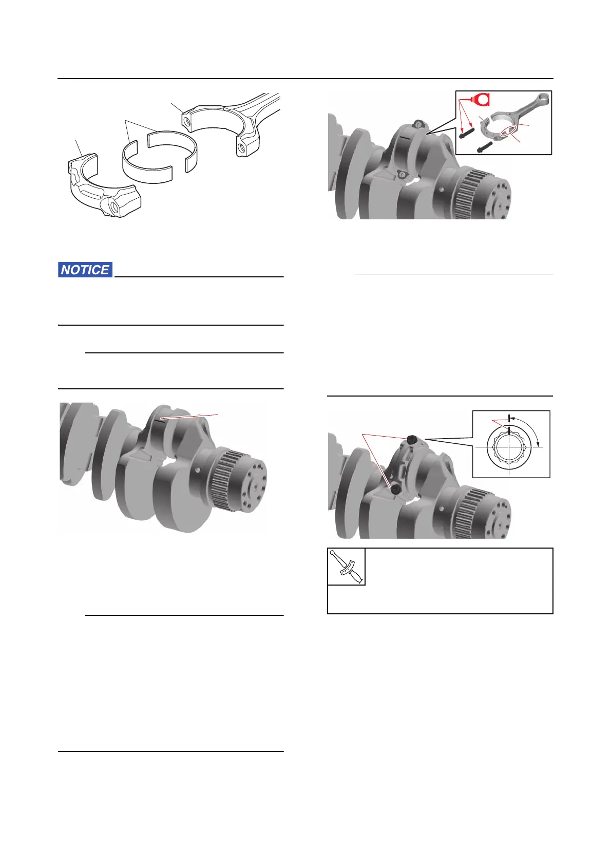
2. Install:
•Plastigauge (PG-1) “1”
Do not place the Plastigauge (PG-1) over
the oil hole in the crankshaft pin of the
crankshaft.
Place a piece of Plastigauge (PG-1) “1” onto
the crankshaft pin, parallel to the crankshaft.
3. Install:
• Connecting rod “1”
• Connecting rod cap “2”
• Connecting rod bolts (temporarily)
• When checking the oil clearance, reuse the
removed connecting rod bolts.
• Make sure that the marks “a” on the con-
necting rod “1” and connecting rod cap “2”
face toward the flywheel magneto end of the
crankshaft.
• Do not turn the connecting rod until the big
end oil clearance measurement has been
completed.
4. Tighten:
• Connecting rod bolts “1”
• Tighten the connecting rod bolts “1” to the
specified torques in 3 stages.
• In the third tightening stage for the connect-
ing rod bolts “1”, mark the connecting rod
bolts and the connecting rod cap with iden-
tification marks “a”, and then tighten the
bolts 90° from the marks on the connecting
rod cap.
5. Remove:
• Connecting rod bolts
• Connecting rod cap
6. Measure:
• Width of the compressed Plastigauge
(PG-1)
Out of specification → Replace the crank-
shaft pin bearing.
Connecting rod bolt “1”
1st: 13 N·m (1.3 kgf·m, 9.6 lb·ft)
2nd: 28 N·m (2.8 kgf·m, 21 lb·ft)
3rd: 90°