8-35
Drive shaft and lower case (regular rotation model)
When the pinion nut “2” is hard to tighten, refer
to the step 2 in “Removing the drive shaft”
(8-28) that indicates the procedure using a rag.
d. Check that the drive shaft turns
smoothly.
2. Install:
• Spacer “1”
• Drive shaft ring nut “2”
The correct setting value of the torque
wrench varies depending on its length.
When tightening the drive shaft ring nut to
the specified torque, use the following cal-
culation formula to obtain the correct set-
ting value.
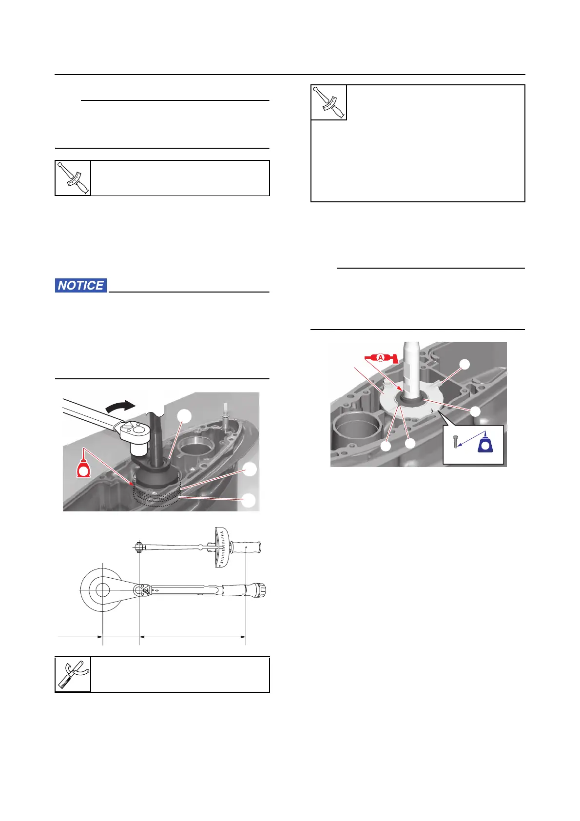
3. Install:
• Oil seal housing assembly “a”
•Cover “1”
• Make sure to install the oil seal housing “a”
so that the protrusion “b” is facing rearward.
• Align the protrusion “c” on the cover “1” with
the slot “d” in the oil seal housing “a”.
Pinion nut “2”
175 N·m (17.5 kgf·m, 129 lb·ft)
Ring nut wrench “3”
90890-06934
3
2
1
GG
Torque wrench setting value =
240 N·m ÷ (A + 0.045) × A
Specified tightening torque for
the drive shaft ring nut
0.045 m
Ring nut wrench length
A m
Torque wrench length
a
b
1
d
c
572572
LTLT