Shimming (regular rotation model)
8-42
A
B
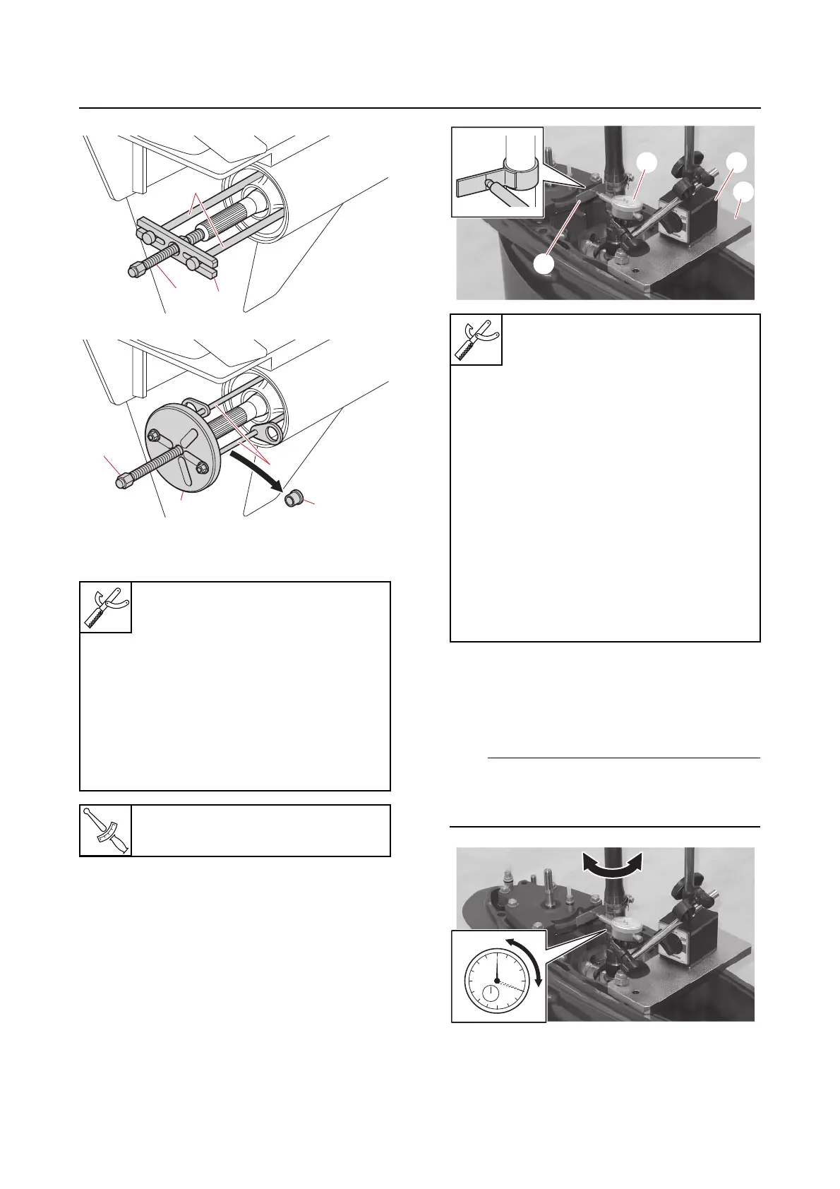
c. Install the special service tool “1” onto
the drive shaft at the lowest possible
position where the shaft diameter is
26.0 mm (1.024 in), and then set up the
special service tools “2”, “3”, and “4”.
d. Turn the drive shaft slowly clockwise
and counterclockwise, and then mea-
sure the backlash between where the
drive shaft stops in each direction.
Do not turn the drive shaft using too much
force. Otherwise, the forward gear will turn,
leading to incorrect measurements.
e. Turn the drive shaft 180° clockwise,
and then measure the backlash again.
A. Worldwide
B. USA and Canada
Center bolt “1”
90890-06504
Bearing housing puller claw L “2”
90890-06502
Stopper guide plate “3”
90890-06501
Bearing housing puller “4”
YB-06207
Universal Puller “5”
YB-06117
Center bolt “1” or “a” (shimming)
4.9 N·m (0.49 kgf·m, 3.6 lb·ft)
Backlash indicator “1”
90890-06836
Magnet base plate “2”
90890-07003
Dial gauge set “3”
90890-03238
Magnet base B “4”
90890-06844
Backlash indicator “1”
YB-06836
Backlash adjustment plate “2”
YB-07003
Dial indicator gauge “3”
YU-03097
Magnetic base stand “4”
YU-A8438