Shimming (counter rotation model)
8-64
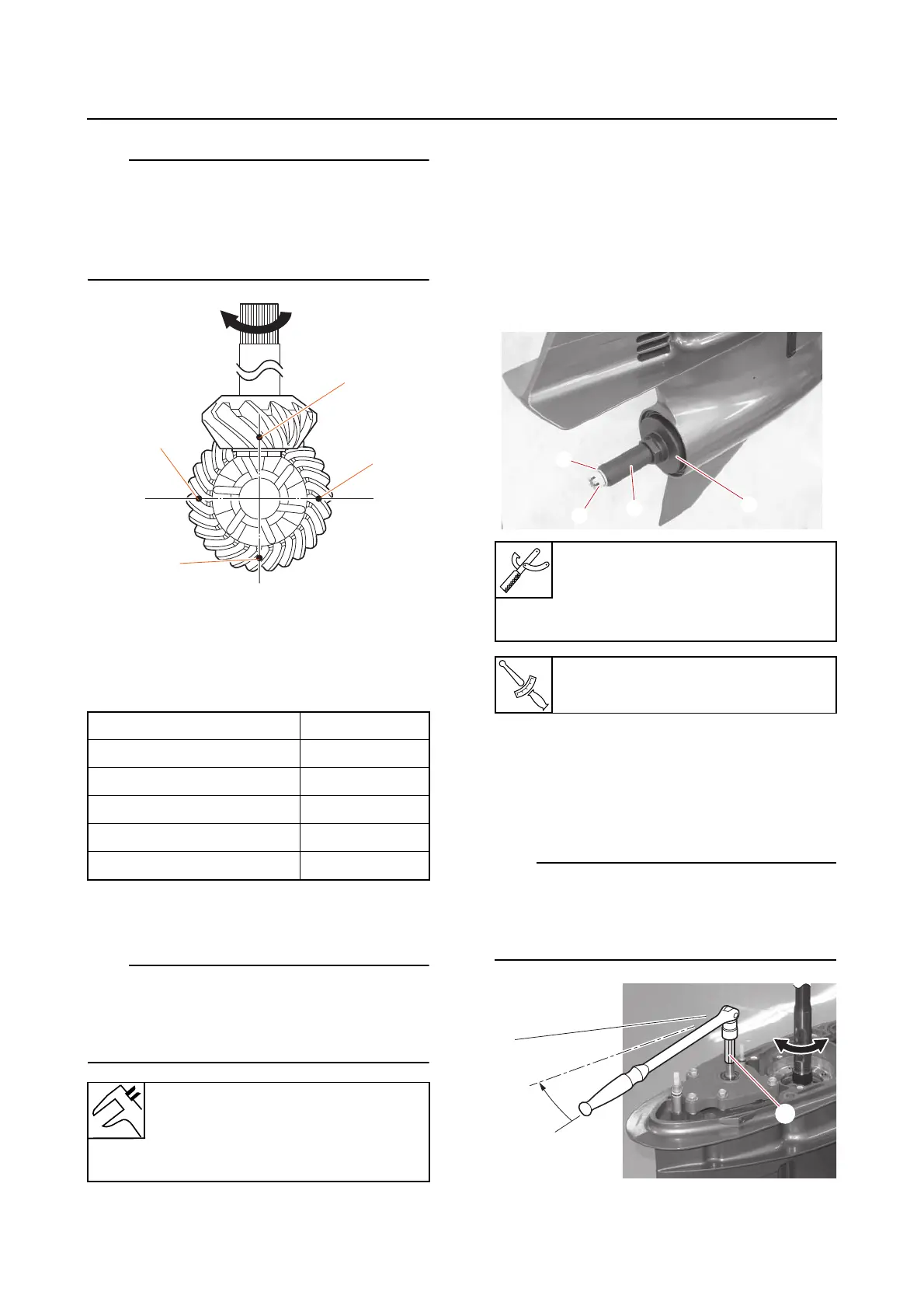
• Measure the backlash at 4 points: “a”, “b”,
“c”, and “d”, turning the drive shaft 180°
clockwise after each measurement.
• Write down the measurement data in the
shimming check sheet.
g. Determine the backlash average, and
then round down the average to 2 dec-
imal places.
(mm)
h. Check that the forward gear backlash
average is within specification.
Repeat steps from the selection of the reverse
gear shim (T1) and forward gear shims (T2) if
the forward gear backlash is out of specifica-
tion.
i. Remove the special service tools from
the propeller shaft.
5. Measure:
• Reverse gear backlash
Out of specification → Repeat steps from
the selection of the reverse gear shim (T1)
and forward gear shims (T2).
a. Install the special service tools “1”, “2”
washer “3”, and propeller nut “4”.
b. While turning the drive shaft, move the
gear shift toward the R position. Set the
shift rod at the position where the pro-
trusion “a” on the dog clutch hits the
protrusion “b” on the reverse gear.
When the protrusion on the dog clutch hits the
protrusion on the reverse gear, the shift rod is
fixed at the position “c” which is in between
the N position and the R position.
Measurement point “a” 0.25
Measurement point “b” 0.26
Measurement point “c” 0.26
Measurement point “d” 0.24
Average 0.2525
Round-down average 0.25
Forward gear backlash
0.20–0.61 mm (0.0079–0.0240
in) (FL400ASTU, FL400ASTX,
FL450AVTU, FL450AVTX)
a
b
c
d
Ring nut wrench “1”
90890-06932
Ring nut extension “2”
90890-06968
Propeller nut “4” (shimming)
10 N·m (1.0 kgf·m, 7.4 lb·ft)