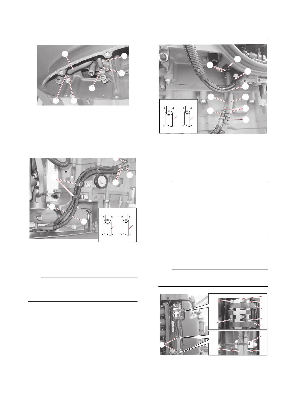
Cooling water hose and gear oil changing hose
9-11
c. Fasten the hose (gear oil) “1” and hose
(air) “2” using the holders “3”.
d. Install the joints “4” and “5” into the
hose (gear oil) “1” and hose (air) “2”,
and then fasten the hoses using new
plastic ties “6”.
e. Route the hose (gear oil) “1” and hose
(air) “2” through the grommet “3”, and
then connect the joints “4” and “5”.
Route the hose (gear oil) “1” and hose (air) “2”
to the inside of the PTT motor lead “6” and
PTT sensor lead “7”.
f. Fasten the hose (gear oil) “1” and hose
(air) “2” using new plastic ties “8”.
g. Install the hose fitting assemblies “a”
and “b” into the hose (gear oil) “1” and
hose (air) “2”, and then install the hose
fitting assemblies “a” and “b” onto the
hose holder “3”.
• Install the hose fitting assemblies “a” and “b”
and hoses “1” and “2” so that the “AIR” and
“OIL” marks are facing outward.
• Make sure that the “AIR” and “OIL” marks on
the hose fitting assemblies “a” and “b” are
positioned next to the corresponding “AIR”
and “OIL” marks on the hose holder “3”.
h. Install the bands “4”.
i. Fasten the hoses “1” and “2” using the
plastic ties “5” as shown.
Do not cut off the excess end of the plastic
ties.
j. Align the white paint marks “a” on the
hose (gear oil) “1” and hose (air) “2”
with the projections “b” on the oil pan
(lower), and then install the cover “3”.
1
5
a
3
1
2
5
b
4
4
2
O I L
A I R
OIL
AIR