Shift actuator and shift rod
9-15
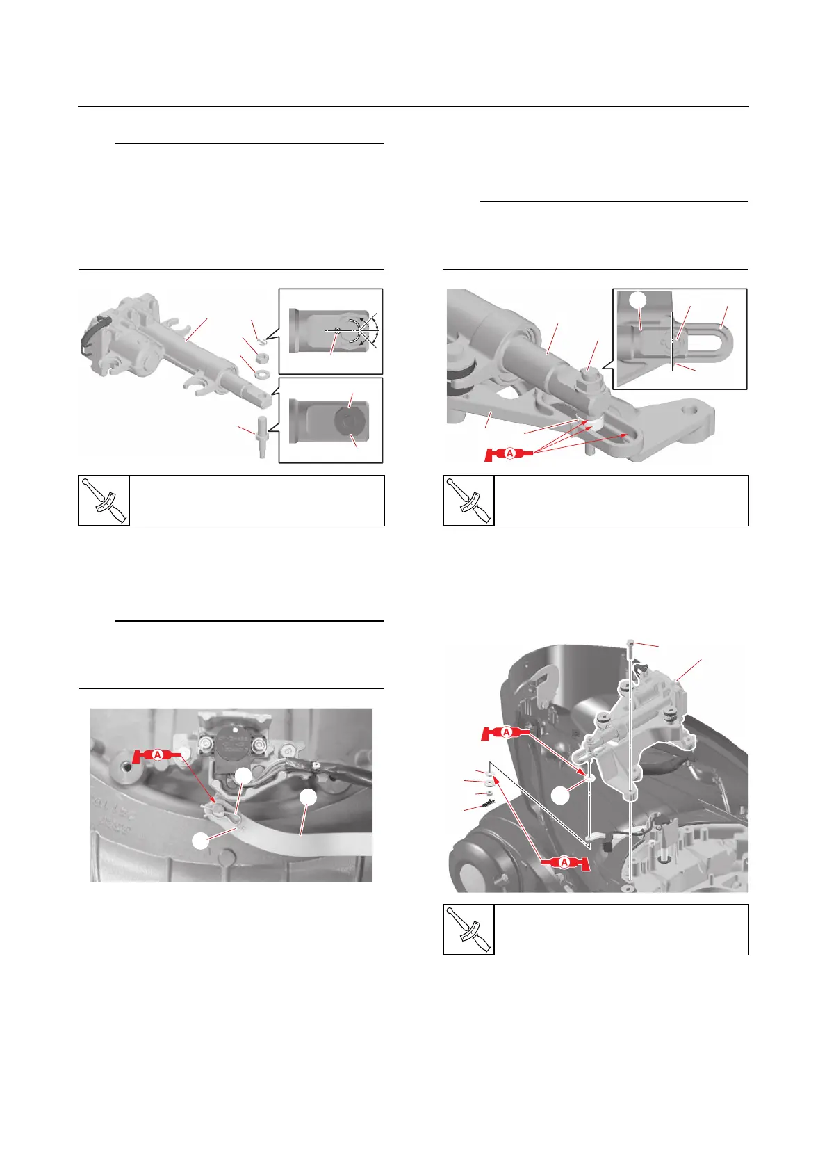
• Install the joint pin “2” so that the flat sides
“a” of the pin are parallel to the sides of the
rod of the shift actuator “1”.
• Install a new cotter pin “5” in the direction
shown and bend the ends 45° or more from
the centerline of the joint pin “2”.
4. Install:
•Shift lever “1”
•Clip “2”
• Make sure that the “6GR” mark “a” on the
shift lever “1” is facing up.
• Install the clip “2” in the direction shown.
5. Assemble:
• Bushing
•Washers
•Grommets
•Collars
•Shift actuator
• Shift bracket
• Bushings
•Washers
• Joint pin nut (lower)
•Clip
a. Install the bushing “1” and shift actua-
tor “2” onto the shift bracket “3”.
Install the shift actuator “2” so that the center
of the joint pin “4” is aligned with the protru-
sion “a” on the shift bracket “3”.
b. Install the bushings “1”, shift actuator
assembly “a”, washer “2”, and joint pin
nut (lower) “3”.
c. Install the clip “4” in the direction
shown.
Joint pin nut (upper) “4”
41 N·m (4.1 kgf·m, 30 lb·ft)
Shift actuator bolt
19 N·m (1.9 kgf·m, 14 lb·ft)
Shift bracket bolt “5”
19 N·m (1.9 kgf·m, 14 lb·ft)