PTT unit
9-47
c. Remove the reservoir cap “1”, and then
check the fluid level in the reservoir.
Before removing the reservoir cap “1”,
make sure that the PTT rams are fully ex-
tended. Otherwise, fluid could be expelled
forcefully from the PTT unit due to internal
pressure.
If the fluid is at the proper level, a small amount
of fluid should flow out of the filler hole.
d. If the fluid is below the proper level,
add the recommended fluid.
e. Install the reservoir cap.
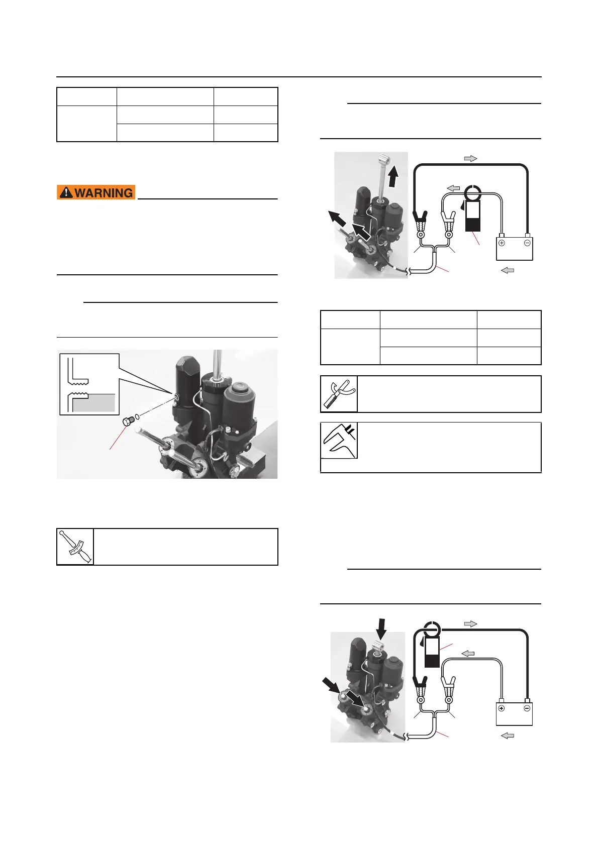
2. Measure:
• PTT motor electric current when the up-
relief valve operates
• PTT motor electric current when the
down-relief valve operates
Out of specification → Check the PTT mo-
tor or PTT gear pump.
See “Checking the PTT motor” (9-53) or
“Checking the gear pump” (9-59).
a. Connect the battery jumper leads to
the PTT motor lead “a” to fully extend
the PTT rams, and then measure the
PTT motor electric current using a
clamp meter “1”.
Use a clamp meter “1” that can measure DC
100 A or more.
b. Connect the battery jumper leads to
the PTT motor lead “a” to fully retract
the PTT rams, and then measure the
PTT motor electric current using the
clamp meter “1”.
Use a clamp meter “1” that can measure DC
100 A or more.
Ram PTT motor lead Battery
Extend
Blue (L) (+)
Green (G) (–)
Reservoir cap
7 N·m (0.7 kgf·m, 5.2 lb·ft)
b. Electric current direction
Ram PTT motor lead Battery
Extend
Blue (L) (+)
Green (G) (–)
Clamp meter “1”
(commercially available)
Electric current
Up
69-93 A
b. Electric current direction