9-60
PTT gear pump
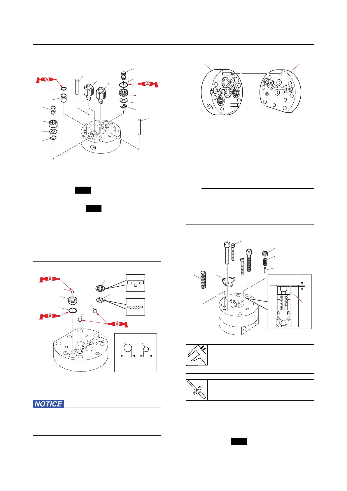
• Valve support pin “9”
2. Install:
• Balls “1”, “2”
• O-ring “3”
• Relief valve seat “4”
• Valve seal “5”
•Valve pin “6”
To prevent the balls “1” and “2” from falling
out of the gear housing assembly, apply a
small amount of grease to the balls.
3. Assemble:
• Gear housing assemblies “a”, “b”
Make sure that there is no gap between the
gear housings. If there is a gap, parts be-
tween them may not be installed properly.
4. Install:
• Spring “1”
•Plate “2”
•Pin “3”
• Spring “4”
• Valve lock screw “5”
• Install the valve lock screw “5” to the depth
“a” that was measured before removing it.
• When installing a new part, install it accord-
ing to the preceding reference data.
5. Install:
• Balls “1”, “2”
• Adapters “a”
• Springs “3”
• O-rings “4”
• Manual release plate “5”
Installation depth “a” (reference
data)
1.35 mm (0.053 in)
Gear pump bolt “6”
1.8 N·m (0.18 kgf·m, 1.3 lb·ft)