A
B
C
D
E
F
G
H
L
M
N
P
section
N 4.1
44 1098/1098S - M.Y. 2007 - edition 00
Engine
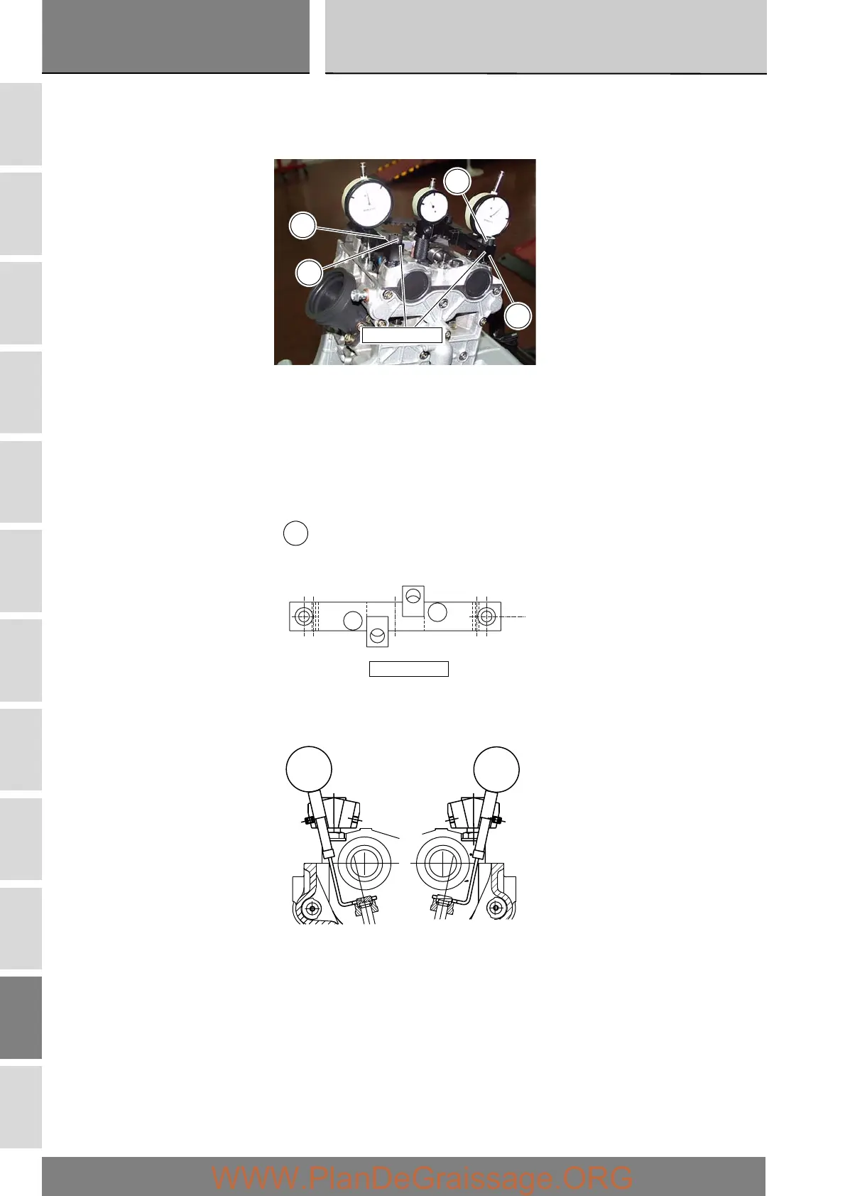
Checking valve lift
Put the engine in the condition described in “Checking and adjusting the valve clearances” above.
Install the dial gauge stand (E) 88765.1518 on the intake side camshaft bearing studs, and secure it with the knobs (F).
Set the opening valve clearance to zero when the camshaft is in its rest position by fitting a feeler gauge between the upper
rocker arm and the opening shim.
Lock the dial gauge into the seat of the stand marked “A” and position the fork probe against the face of the closing shim.
Set the dial gauge to zero when the valve is fully closed.
Rotate the intake camshaft so as to allow the intake valves to lift fully.
Check that the reading on the dial gauge corresponds to the specified value (Sect. C 1.1).
Repeat the same procedure with the exhaust valves, moving the stand to the opposite studs and fitting the dial gauge into the
seat marked “S” on the stand (E).
88765.1518
E
F
F
E
A
S
88765.1518
E