A
B
C
D
E
F
G
H
L
M
N
P
section
D 5
84 1098/1098S - M.Y. 2007 - edition 00
Use and maintenance
Testing the battery charging system
Notes
The on-screen icons used during this procedure are explained in a table at the end of this section.
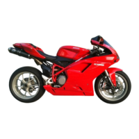
You can determine the engine rpm required for the alternator to produce sufficient current to charge battery, power the injection/
ignition system and all the electrical equipment on the motorcycle. When applied to a cable, the ammeter clamp (18) detects the
magnetic field generated by the current passing through that cable.
Remove the right-hand fairing (Sect. E 2).
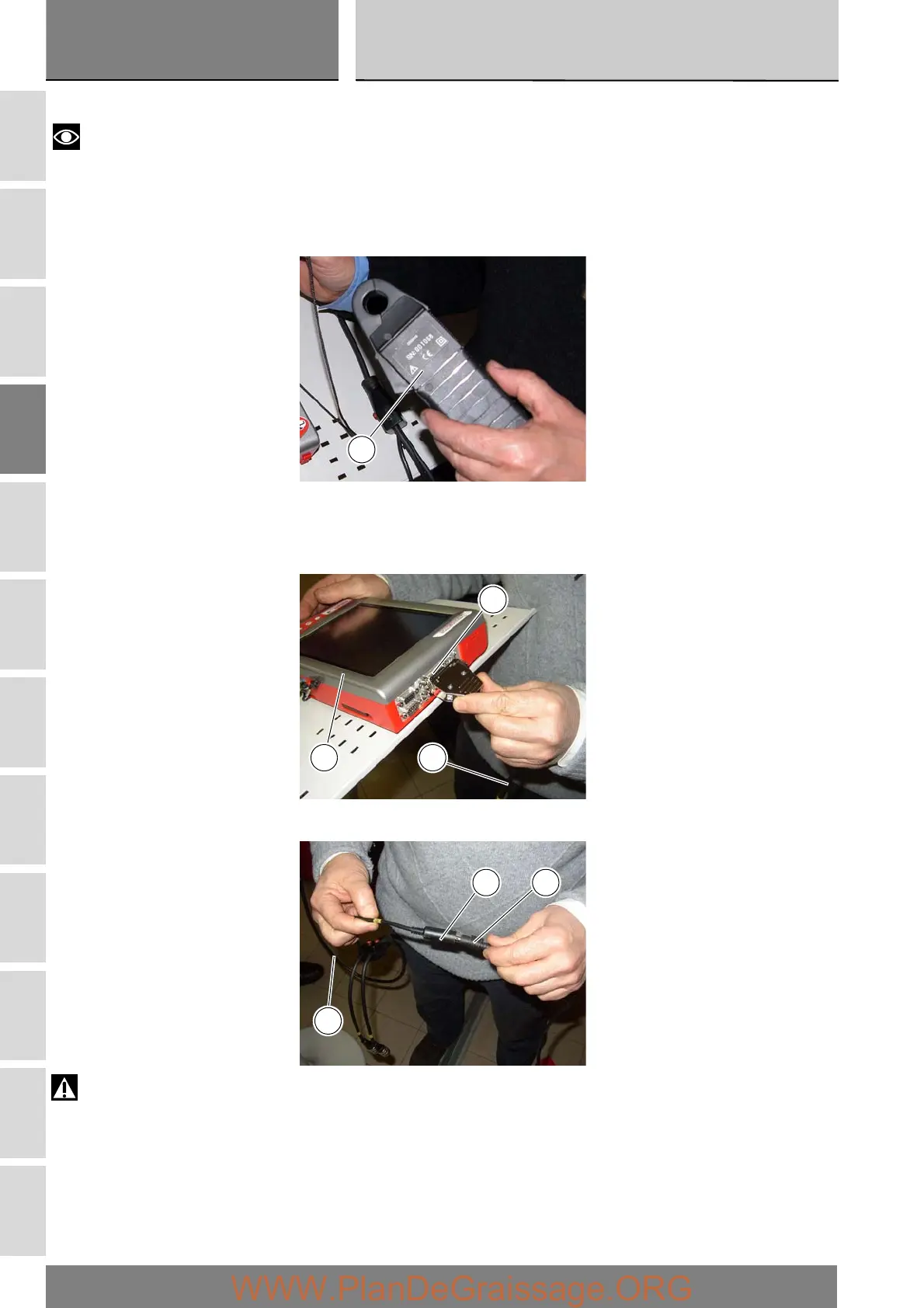
Switch on the DDS tester (1); see heading “Tester power supply”.
Connect the power and diagnostics cable (Measurement Module) (3) to the measurement module connector (D) on the DDS
tester (1).
Connect the ammeter clamp to the connector (E) of the power and diagnostics cable (Measurement Module) (3).
Warning
The ammeter clamp must not be connected to wires through which electrical current is flowing.
Apply the ammeter clamp to the battery positive terminal lead with the arrow on the clamp pointing towards the battery positive
terminal (+).
18
D
1 3
E
3
15