A
B
C
D
E
F
G
H
L
M
N
P
section
N 4.5
871098/1098S - M.Y. 2007 - edition 00
Engine
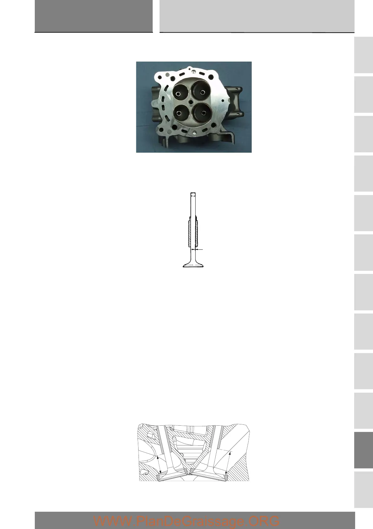
Valve guides
Check the inner surface of the valve guides for cracking or distortion.
Thoroughly check the dimensions of the inner surface of the valve guide. Measure the inside diameter with a bore diameter
gauge.
Measure the diameter at different positions of the valve guide.
The assembly clearance must be:
highest measured value – lowest measured value = 0.03 to 0.045 mm.
The maximum permissible wear limit is 0.08 mm.
Change the valve guides when the ovality exceeds permissible limit or the clearance to the valve stem is outside the tolerance
range.
When you change the valve guide, you must also change the valve.
Replacement valve guides are available with outside diameter oversizes of 0.03, 0.06 and 0.09 mm.
Change the valve guides as follows:
heat up the cylinder head gradually and evenly up to 150 °C.
remove the original valve guides using drift part no. 88713.2842;
allow the cylinder head to cool down and check the condition of the seats.
select the most suitable valve guide so as to obtain an assembly clearance with the cylinder head of 0.022 to 0.051 mm; heat the
cylinder head up again and chill the new valve guides with dry ice;
lubricate the seats in the head and install the valve guides using the appropriate service tools and referring to dimension given in
the figure;
A= 22.4±0.15 mm.
B= 28.45±0.15 mm.
Hone the mating surface with a reamer.
A
B
 Loading...