A
B
C
D
E
F
G
H
L
M
N
P
section
P 5
66 1098/1098S - M.Y. 2007 - edition 00
Electric system
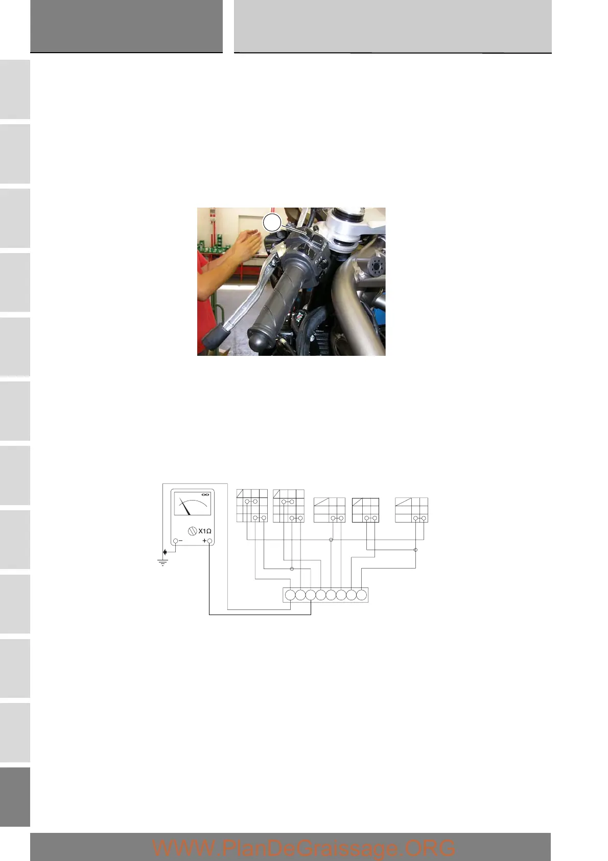
Turn signal switch (TURN)
Connect the multimeter to the Orange and Green wires from the turn signal switch and check for electrical continuity when
operating the right turn signals (see Sect. P 9, Diagnostic instruments concerning operation of the multimeter). Repeat the above
procedure for the left turn signal but connect the multimeter to the Green and Orange wires. The above colours refer to the colour
of wires from the switch and not to the colour of wires of the main electrical system.
Low and high beam headlights (DIMMER)
The test method is the same; connect the meter to the Red/Blue and Light blue/Yellow wires.
Control switch (MODE)
Connect the multimeter to the Blue/Yellow and Orange wires from the function selector switch and check that there is electrical
continuity when the pushbutton (A) is pressed (Sect. P 9, Diagnostic instruments – multimeter operation). Repeat the same
procedure, operating the pushbutton (A) in the remaining position and conecting the multimeter to the Brown and Blue/Yellow
wires.
Flasher (PASSING)
Check for continuity across the Red/Blue and Brown wires.
A
LY
Br
OFF
PUSH
GO
N
Gy
L
HI
LO
R
OFF
PUSH
TURN HORN DIMMER PASSING
--------
Br BY
N
O
A
B
MODE
Br BW
RB
RB