4 - 199
Chapter 4 Disassembly / Assembly and Adjustments
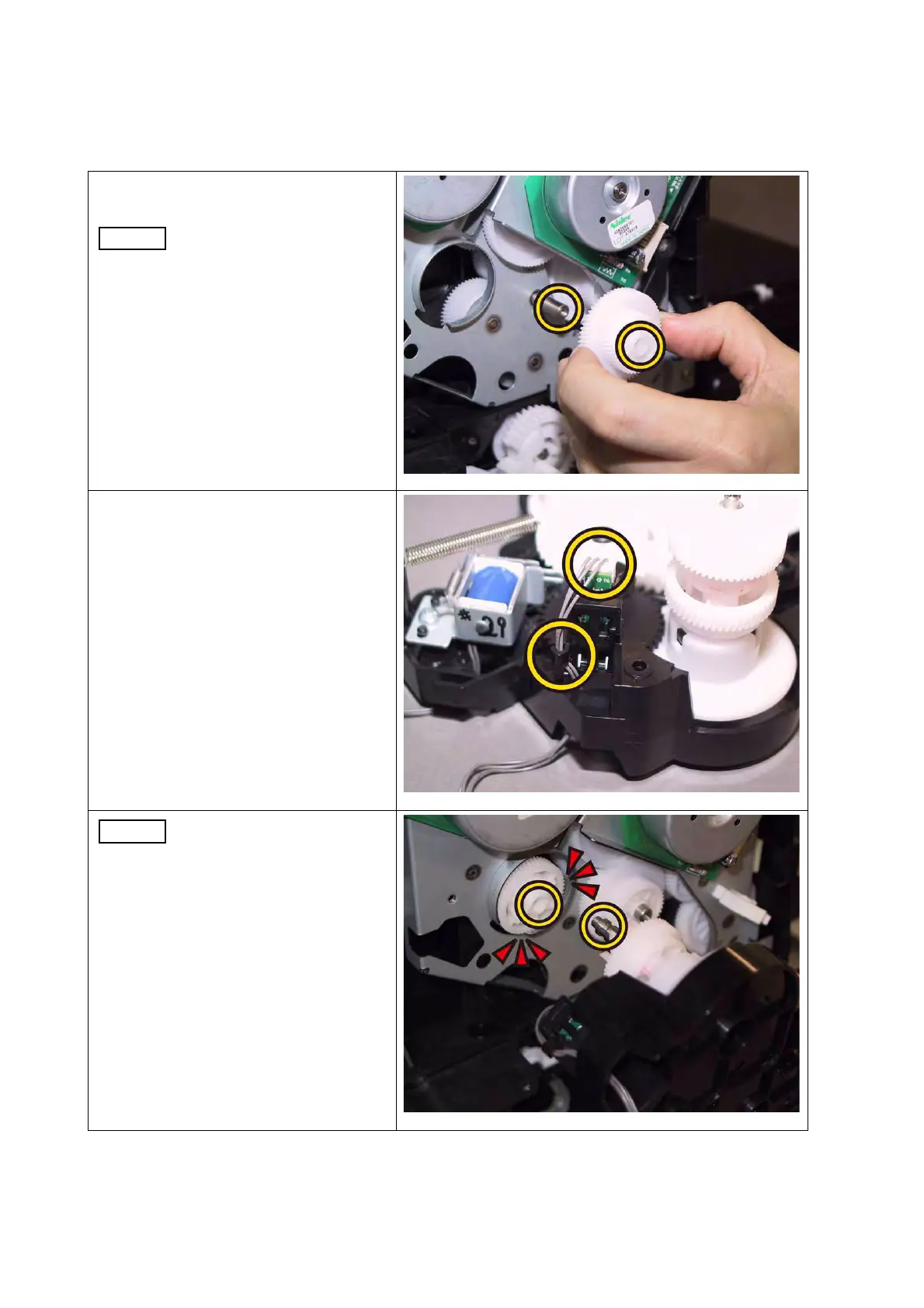
[Replacement]
1) Attach the GEAR P2 to the shaft of
DRIVE ASSY SUB.
Ensure that the GEAR P2 is
oriented to the direction
shown in the right.
2) Replace the SENSOR PHOTO:
COLOR MODE SWITCHING to the
DRIVE ASST PH by mating the
three hooks of the SENSOR
PHOTO: COLOR MODE SWITCH-
ING with its mounting position.
3) Engage the connector (J261) of the
HARN ASSY KSNR REGCL MG
AIO with the Color mode switching
sensor of the DRIVE ASSY PH,
route the HARN ASSY KSNR
REGCL MG AIO through the hook
of the DRIVE ASSY PH.
When carrying out the work
described next procedure,
take care not to drop the
coupling gear to inside.
 Loading...