4 - 229
Chapter 4 Disassembly / Assembly and Adjustments
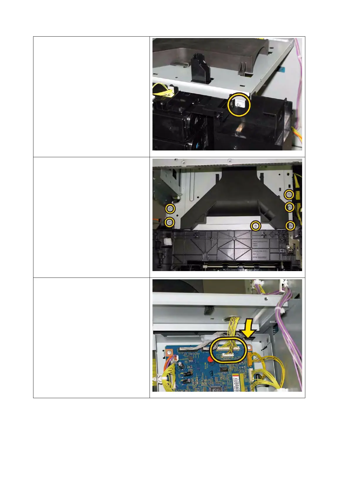
4) Secure the right side of the PLATE
ASSY TOP with the one screw (sil-
ver, tap, 8mm).
5) Secure the upper side of the PLATE
ASSY TOP with the six screws (sil-
ver, tap, 8mm).
6) Route the HARNESS ASSY ESS
MG AIO (PL9.1.1) and the HAR-
NESS ASSY ESS VIDEO MG AIO
(PL9.1.2) through the hole of the
PLATE ASSY TOP, engage the two
connectors (P/J10 and 11) with the
PWBA MCU.
 Loading...