3: Functions and features Model DMM7510 7½ Digit Graphical Sampling Multimeter
3-48 DMM7510-901-01 Rev. B / May 2015
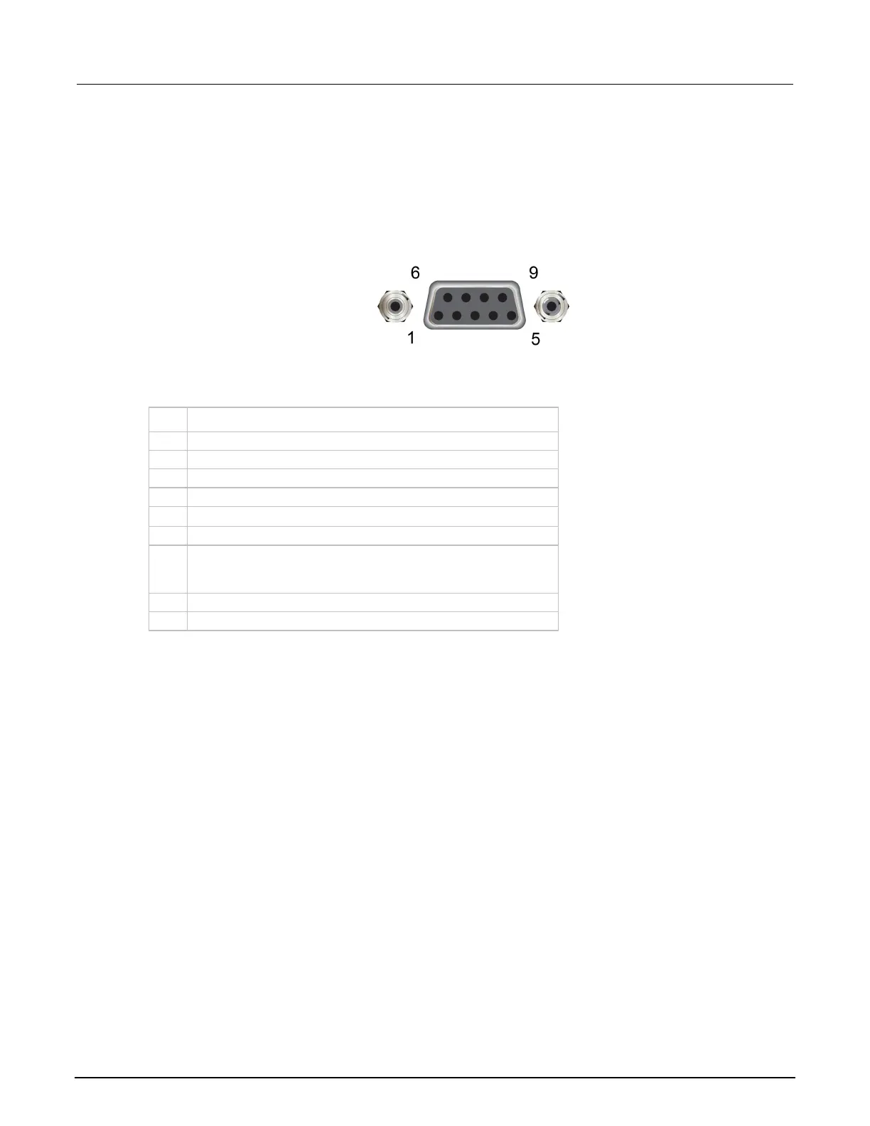
Digital I/O connector and pinouts
The digital I/O port uses a standard female DB-9 connector, which is located on the rear panel of the
Model DMM7510. You can connect to the Model DMM7510 digital I/O using a standard male DB-9
connector. The port provides a connection point to each of the six digital I/O lines and other
connections as shown in the following table.
Figure 120: Model DMM7510 digital I/O port
Model DMM7510 digital I/O port pinouts
Pin Description
V
ext
line (relay flyback diode protection; maximum 33 V)
7 +5 V line. Use this pin to drive external logic circuitry. Maximum
current output is 500 mA. This line is protected by a self-
resetting fuse (one-hour recovery time).
 Loading...


