7½ Digit Graphical Sampling Multimeter Reference Manual Section 3:
DMM7510-901-01 Rev. B / May 2015 3-57
To use the trigger model as a stimulus to a digital I/O line, you can use the trigger model Notify
block. For information on the Notify block, see Notify block (on page 3-83).
Digital I/O bit weighting
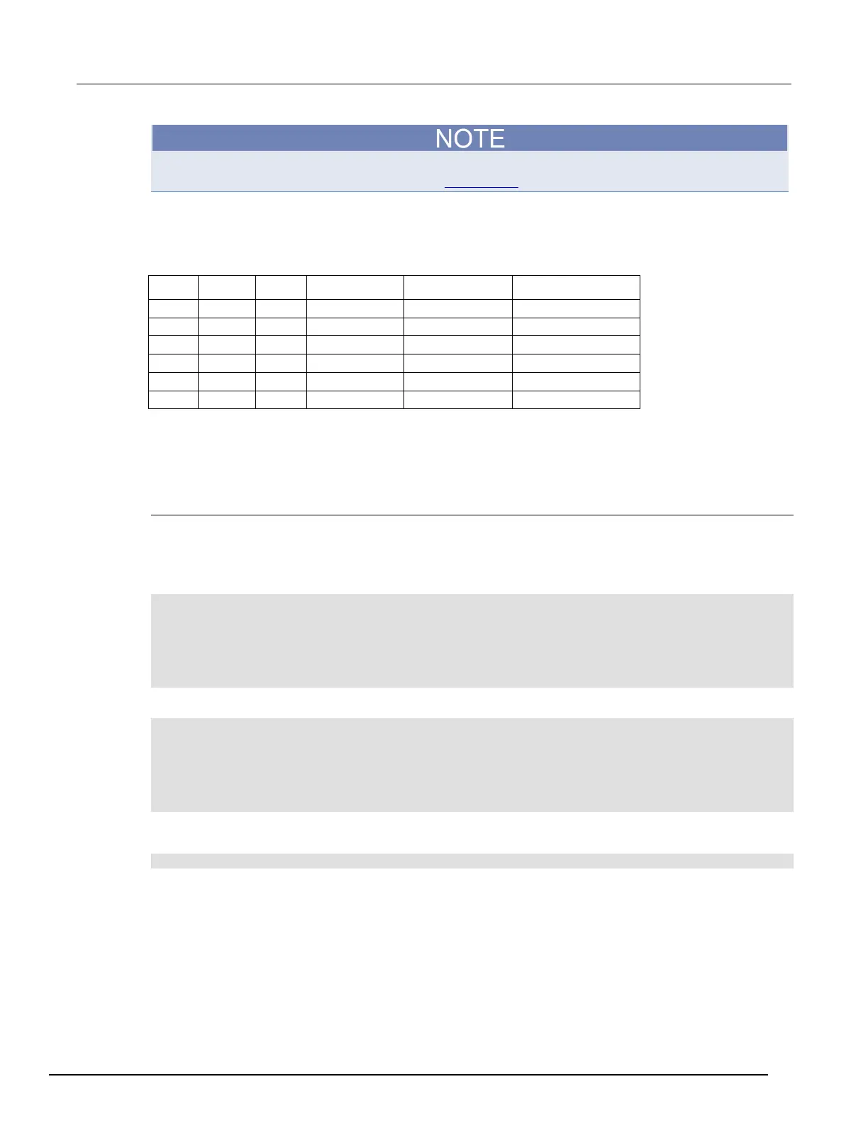
Bit weighting for the digital I/O lines is shown in the following table. Line 1 is the least significant bit.
Line # Bit Pin Decimal Hexadecimal Binary
Digital I/O programming examples
These examples provide typical methods you can use to work with the digital I/O port.
Outputting a bit pattern
The programming examples below illustrate how to output the bit pattern 110101 at the digital I/O
port. Line 1 (bit 1) is the least significant bit.
Using SCPI commands to configure all six lines as digital outputs:
:DIGital:LINE1:MODE DIGital, OUT
:DIGital:LINE2:MODE DIGital, OUT
:DIGital:LINE3:MODE DIGital, OUT
:DIGital:LINE4:MODE DIGital, OUT
:DIGital:LINE5:MODE DIGital, OUT
:DIGital:LINE6:MODE DIGital, OUT
Using SCPI commands to set the state of each line individually:
:DIGital:LINE6:STATe 1
:DIGital:LINE5:STATe 1
:DIGital:LINE4:STATe 0
:DIGital:LINE3:STATe 1
:DIGital:LINE2:STATe 0
:DIGital:LINE1:STATe 1
Using SCPI commands to set all six lines at once by writing the decimal equivalent of the bit pattern to
the port :
:DIGital:WRITe 53
 Loading...


