Programming technology functions (cycles)
8.4 Milling
Turning
Operating Manual, 03/2013, 6FC5398-8CP40-3BA1
403
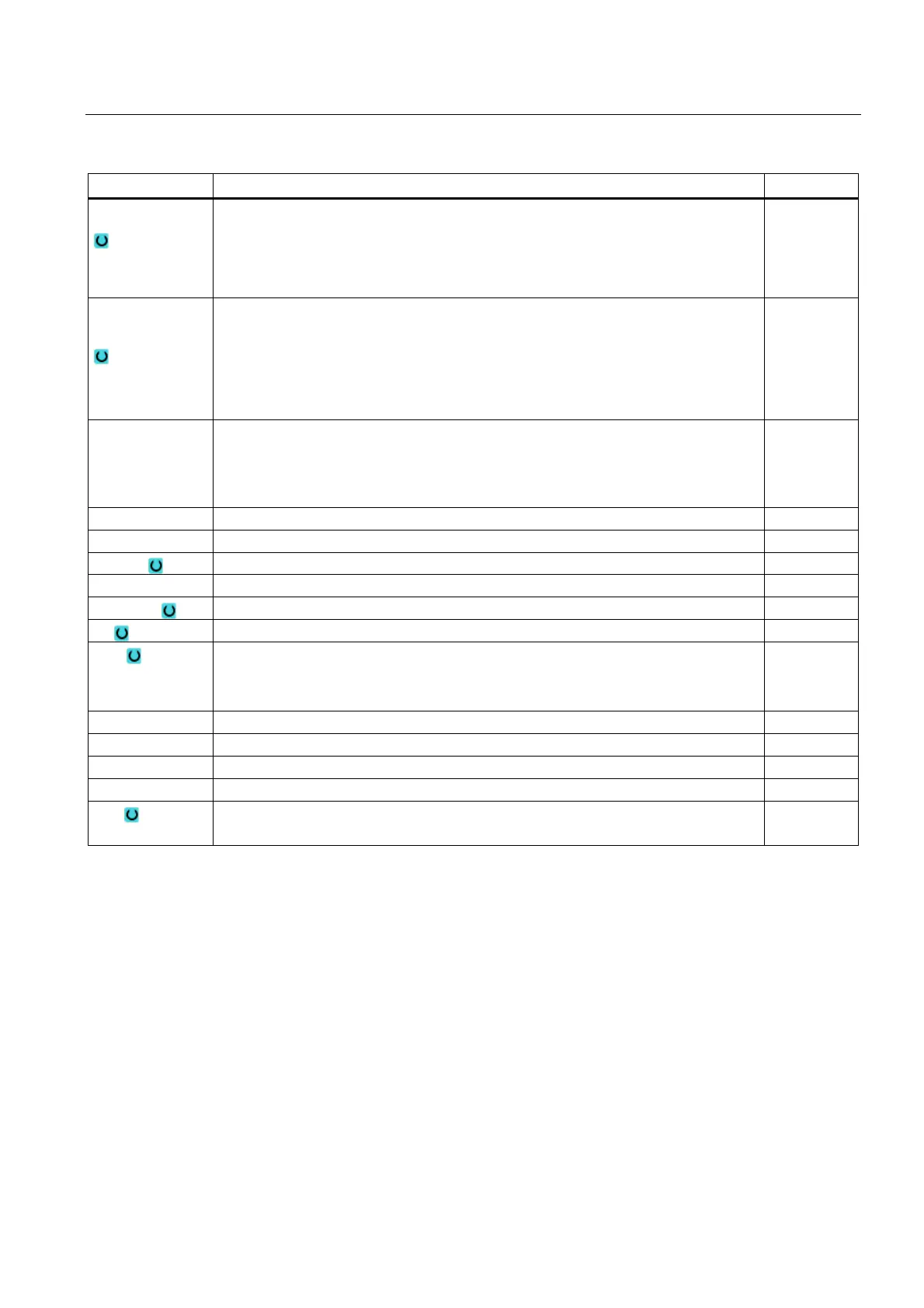
Parameter Description Unit
Machining
• ∇ (roughing)
• ∇∇∇ (finishing)
• ∇∇∇ edge (edge finishing)
• Chamfering
Machining
position
(only for G code)
• Single position
A multiple edge is milled at the programmed position (X0, Y0, Z0).
• Position pattern
Several multiple edges are milled at the programmed position pattern (e.g. pitch
circle, grid, line).
X0 (only G code)
Y0 (only G code)
Z0
The positions refer to the reference point:
Reference point X – (only for single position)
Reference point Y – (only for single position)
Reference point Z – (only for single position)
mm
mm
mm
∅ Diameter of blank spigot mm
N Number of edges
SW or L Width across flats or edge length mm
α0 Angle of rotation Degrees
R1 or FS1 Rounding radius or chamfer width mm
Z1 Multi-edge depth (abs) or depth in relation to Z0 (inc) - (only for ∇, ∇∇∇ and ∇∇∇ edge) mm
DXY
• Maximum plane infeed
• Maximum plane infeed as a percentage of the milling cutter diameter
- (only for ∇ and ∇∇∇)
mm
%
DZ Maximum depth infeed - (only for ∇ and ∇∇∇) mm
UXY Plane finishing allowance - (only for ∇, ∇∇∇ and ∇∇∇ edge) mm
UZ Depth finishing allowance – (only for ∇ and ∇∇∇) mm
FS Chamfer width for chamfering - (for chamfering only) mm
ZFS Insertion depth of tool tip (abs or inc) - (for chamfering only) mm
%
* Unit of feedrate as programmed before the cycle call