Programming technology functions (cycles)
8.5 Contour milling
Turning
466 Operating Manual, 03/2013, 6FC5398-8CP40-3BA1
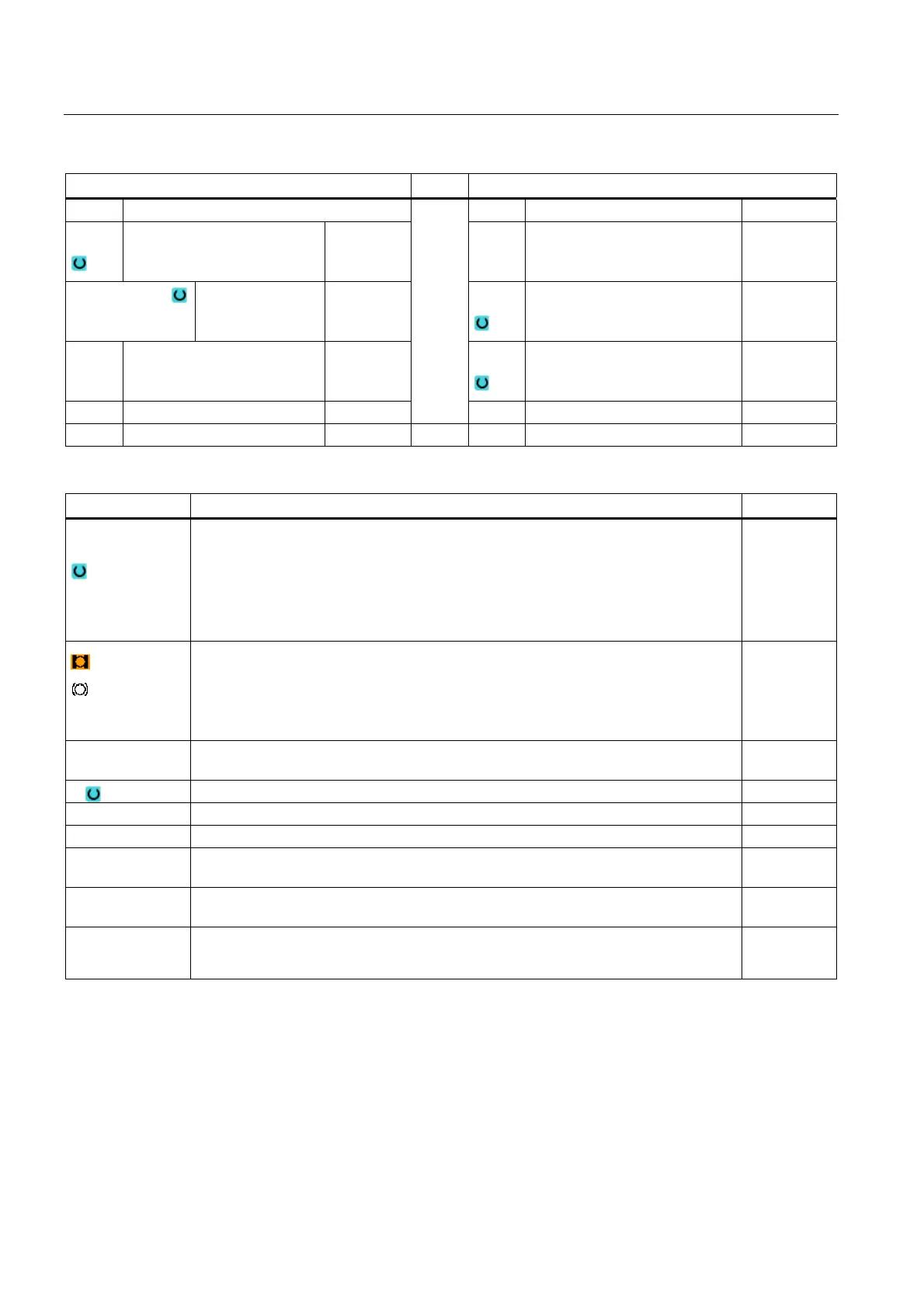
Parameters, G code program Parameters, ShopTurn program
PRG Name of the program to be generated T Tool name
PL
Machining plane D Cutting edge number
Milling direction
• Climbing
• Conventional
F
Feedrate mm/min
mm/tooth
RP Retraction plane mm S / V
Spindle speed or constant
cutting rate
rpm
m/min
SC Safety clearance mm
F Feedrate mm/min
parameters Description Unit
Machining
surface
(only for
ShopTurn)
• Face C
• Face Y
• Face B
• Peripheral surface C
• Peripheral surface Y
(only for
ShopTurn)
Clamp/release spindle (only for end face Y/B and peripheral surface Y)
The function must be set up by the machine manufacturer.
TR Reference tool Tool, which is used in the "stock removal" machining step. This is used
to determine the residual corners.
D Cutting edge number
Z0 Reference point in the tool axis Z mm
Z1 Pocket depth (abs) or depth referred to Z0 or X0 (inc) mm
CP Positioning angle for machining area
- (only for ShopTurn, machining surface, face Y)
Degrees
C0 Positioning angle for machining surface
- (only for ShopTurn, machining surface, peripheral surface Y)
Degrees
DXY
• Maximum plane infeed
• Maximum plane infeed as a percentage of the milling cutter diameter
mm
%