Programming technology functions (cycles)
9.6 Further cycles and functions
Turning
560 Operating Manual, 01/2015, 6FC5398-8CP40-5BA2
Also in the basic setting (pole setting) of the machine kinematics, the NC calculates two
solutions and these are approached by CYCLE800. The reference is the rotary axis that was
set as direction reference when commissioning the "swivel" function.
he machine manufacturer's specifications.
If one of the two positions cannot be reached for mechanical reasons, the alternative position
is automatically selected irrespective of the setting of the "Direction" parameter.
Example:
● Machine kinematics with swivel head and swivel table.
Swivel head with rotary axis 1 (B) rotates around machine axis Y.
● Angular traversing range of rotary axis B from -90 to +90 degrees.
● Swivel table with rotary axis 2 (C) rotates around machine axis Z.
● Angle traversing range of rotary axis 2 (C) from 0 to 360 degrees (modulo 360).
● Machine manufacturer has set the direction reference to rotary axis 1 (B) when he
commissioned the swivel function.
● A rotation around X (WCS) of 10 degrees is programmed in the swivel cycle.
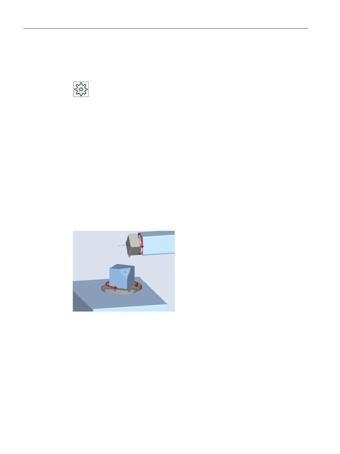
The machine in the basic setting (pole setting) of the kinematics (B = 0 C = 0) is shown in the
following diagram.
● Direction "-" (minus)
– Rotary axis B moves to -10 degrees in the negative direction (red arrow).
– Rotary axis C moves to 90 degrees (rotation around X!).
● Direction "+" (plus)
– Rotary axis B moves to +10 degrees in the positive direction (red arrow).
– Rotary axis C moves to 270 degrees.
The two "Minus" or "Plus" direction settings enable a workpiece to be machined with
swiveled planes. The two solutions calculated by the NC differ by 180 degrees (see rotary
axis C).