Service Parts Disassembly
Phaser 3610, WorkCentre 3615 Service Manual4-16
REP 1.7 Left Side Cover (3610)
PL 1.1 Covers (3610)
Removal
WARNING: Allow the Fusing Assembly to cool before servicing the product.
1. Remove (REP 1.4 Top Cover Assembly (3610)).
2. Release the thumb screw to remove the ESS PWB Cover from the left side of the machine.
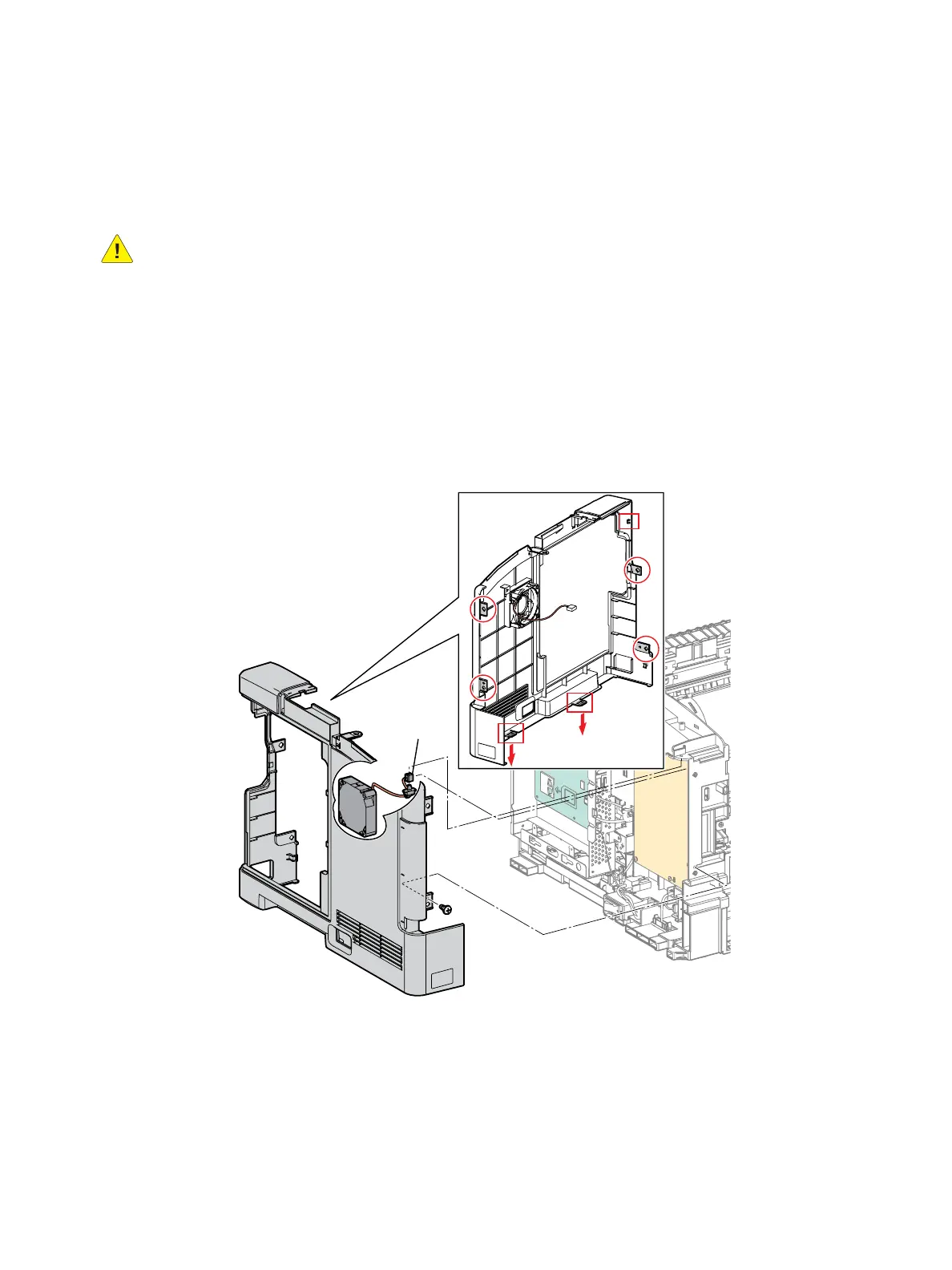
3. Remove the Left Side Cover. (Figure 1)
a. Remove 1 screw (silver, tapping, 8mm).
b. Release 4 bosses.
c. Release 3 clips that secure the cover to the chassis.
d. Release the fan cable tie, disconnect P/J241 from the LVPS.
e. Remove the cover.
Figure 1
Replacement
1. Connect P/J 241 and re-install the cable tie.
2. Secure the clips on the bottom of the cover first, before engaging the remaining clips and bosses.
3. Replace in reverse order.
s3610-010
P/J241
a)
c)
d)
e)
b)

 Loading...