Service Parts Disassembly
Phaser 3610, WorkCentre 3615 Service Manual4-108
REP 5.7 HVPS (3610)
PL 5.3 Electrical (MCU PWB / HVPS)
Removal
WARNING: Allow the Fusing Assembly to cool before servicing the product.
CAUTION: Do not remove the HVPS from the protective bag until ready for installation. Always
wear a grounded wrist band while handling circuit boards.
1. Remove the Bypass Tray.
2. Remove (REP 1.2 Front Cover Assembly (3610 / 3615)).
3. Open the Rear Cover, release the stopper strap and hinge clip from the chassis and rest the Rear
Cover Assembly on the work surface.
4. Remove (REP 1.4 Top Cover Assembly (3610)).
5. Remove (REP 1.6 Right Side Cover (3610)).
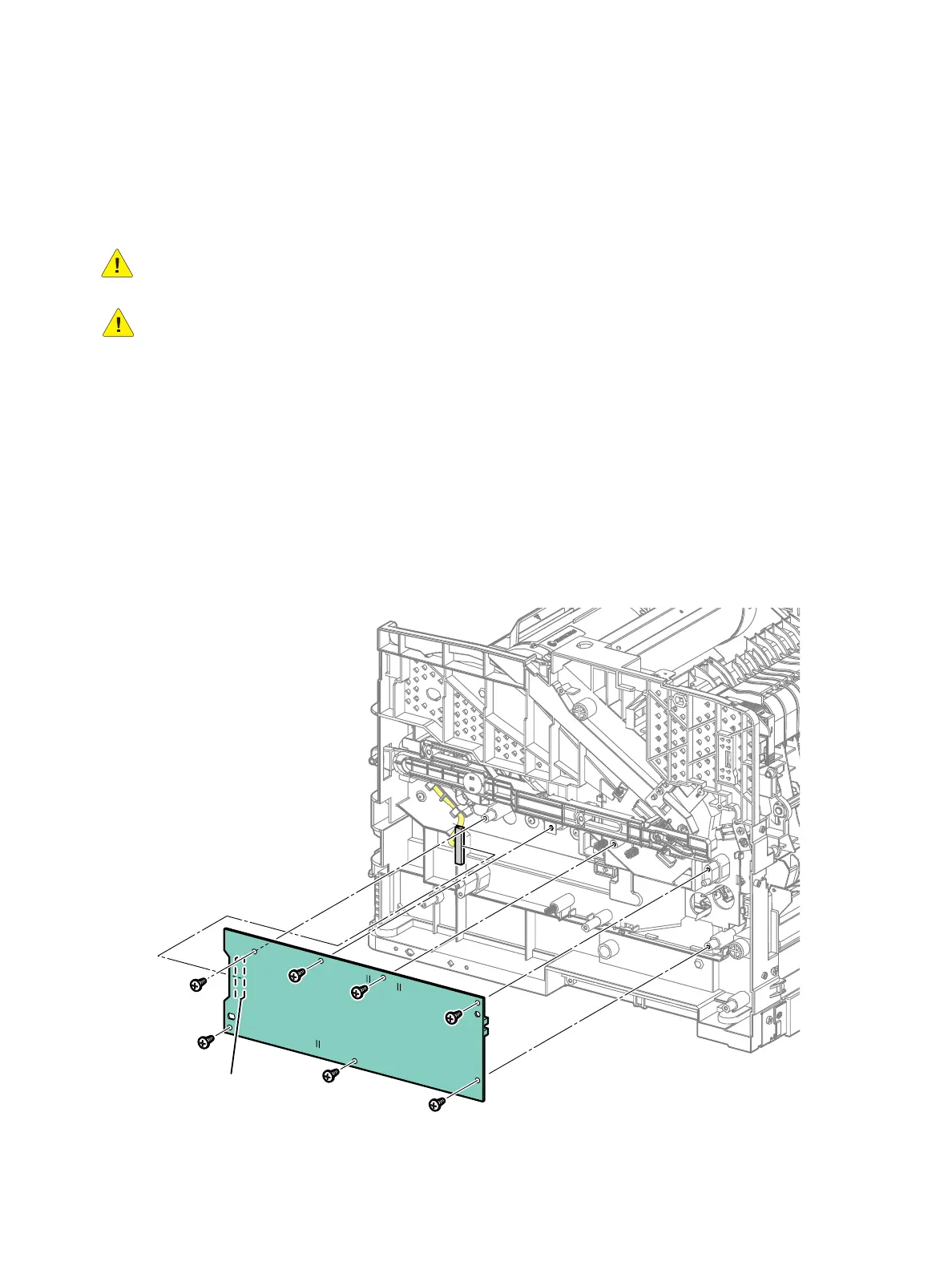
6. Remove the HVPS. (Figure 1)
a. Remove 7 screws (silver, tapping, 8mm) to remove the HVPS from the chassis.
b. Disconnect P/J261 from the inboard side of the HVPS.
Figure 1
s3610-072
P/J261
b)
a)

 Loading...