Service Parts Disassembly
Phaser 3610, WorkCentre 3615 Service Manual4-58
REP 2.11 Exit Chute Assembly
PL 2.5 Exit Chute
Removal
1. Open the Front Cover.
2. Open the Rear Cover.
Note: For the 3615, depending on your tool set, you may need to remove the (REP 6.1 IIT
Assembly)
3. Remove (REP 1.1 Control Panel (3610)).
4. Remove (REP 1.4 Top Cover Assembly (3610))
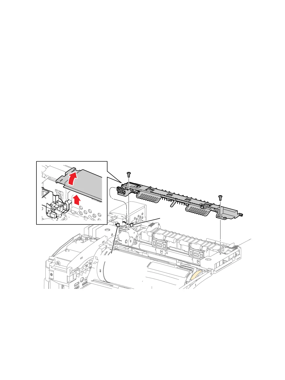
5. Remove the Exit Chute Assembly. (Figure 1)
a. Remove 2 screws (silver, M3, 6mm) that secure Exit Chute Assembly to the chassis.
b. Lift the chute in the direction of the arrow to disconnect P/J271 and 272.
c. Flex the Left Side Cover to release 2 bosses.
Figure 1
s3610-032
P/J271
P/J272

 Loading...