Outboard motor mounting
3-9
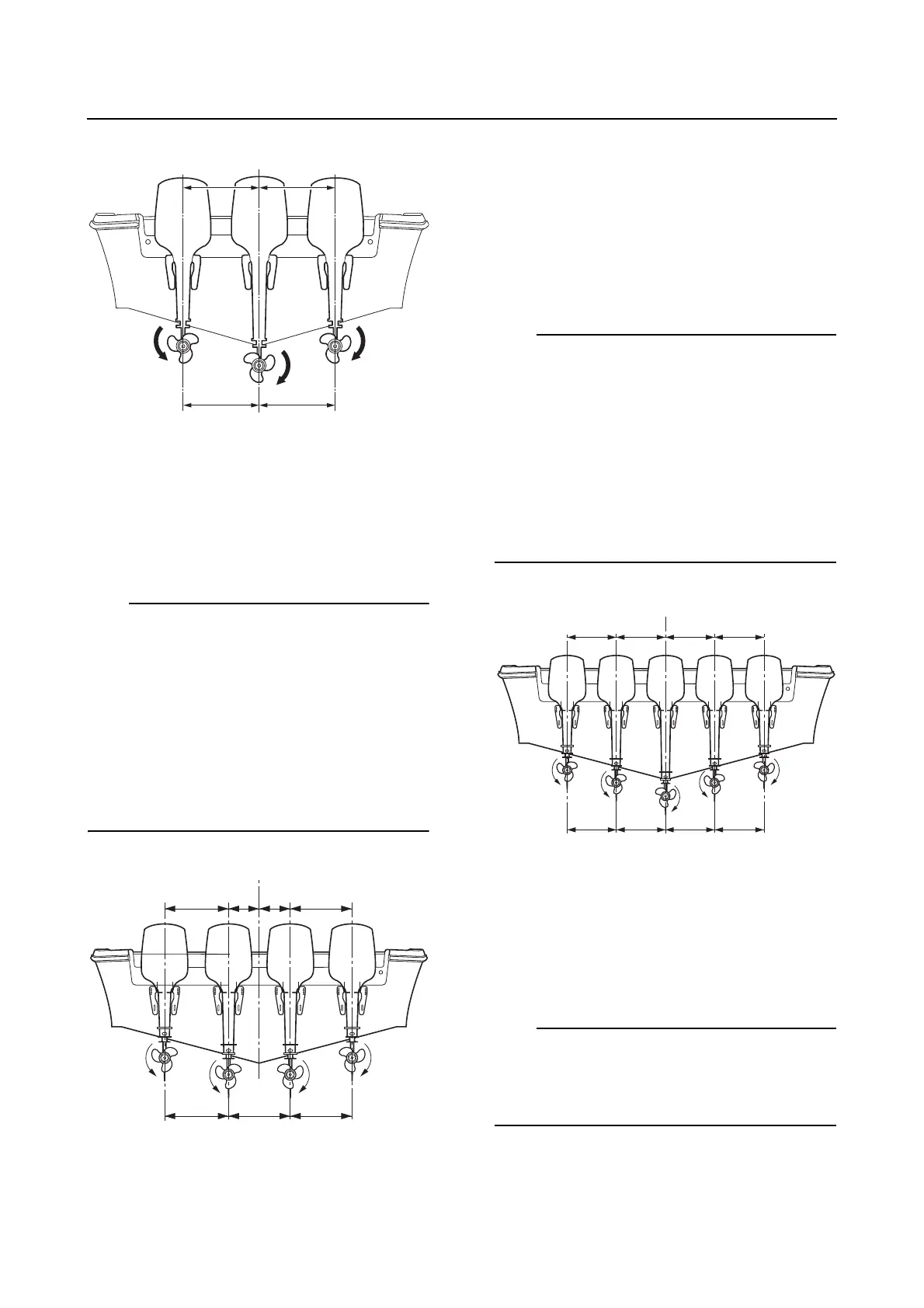
For a quad outboard motor application,
place the outboard motors so that the dis-
tance from the C/L of each outboard mo-
tor to the C/L of the boat transom are
equal on both sides.
• Make sure that the distance “i” is equal to
distance “j”.
• Make sure that the distance “k” is equal to
distance “l”.
• If the boat has a V shape hull, the center out-
board motors should have a longer transom
height than the outboard motors on both
sides.
• For the distance (T1), see “External dimen-
sions” (1-2).
For a quint outboard motor application,
place the center outboard motor so that
the C/L of the outboard motor is aligned
with the C/L of the boat transom. Place
the other four outboard motors so that the
distance from the C/L of each outboard
motor to the C/L of the boat transom are
equal on both sides.
• Make sure that the distance “m” is equal to
distance “n”.
• Make sure that the distance “o” is equal to
distance “p”.
• If the boat has a V shape hull, the center out-
board motors should have a longer transom
height than the outboard motors on both
sides.
• For the distance (T1), see “External dimen-
sions” (1-2).
2. Adjust the position of the outboard motor
so that the height of the anti-cavitation
plate “1” is equal to the bottom of the boat
transom.
This mounting height information is for refer-
ence only. It is impossible to provide complete
instructions for every possible boat and out-
board motor combination.
C/L.Centerline of the transom
C/L.Centerline of the transom
C/L.Centerline of the transom
C/L
omn p
(T1) (T1)(T1) (T1)