7-10
Exhaust joint (outside)
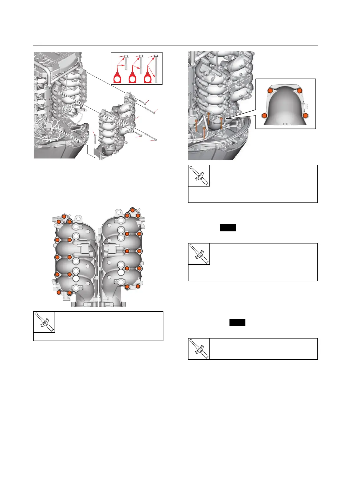
c. Tighten the exhaust joint assembly
bolts (PORT and STBD) to the speci-
fied torque in the order [1], [2], and so
on.
d. Tighten the exhaust joint assembly
bolts (lower) to the specified torques in
2 stages and in the order [1], [2], and so
on.
3. Install:
• Exhaust joint anode
•O-ring
• Exhaust joint anode plug
4. Install:
• Water pressure sensor
•Pilot hose
• Pilot hose joint
•Plastic tie
• Pilot hose holder
5. Connect:
• Water pressure sensor coupler
6. Install:
•Fuel rail cover
See “Fuel hose assembly” (6-12).
• Bottom cowling
See “Installing the bottom cowling” (9-7).
• Bottom cowling cover
See “Bottom cowling cover and apron
cover” (9-1).
Exhaust joint assembly bolt
(PORT and STBD)
21 N·m (2.1 kgf·m, 15 lb·ft)
[10][10]
[11][11]
[9][9]
[11][11]
[6][6]
[2][2]
[3][3]
[7][7]
[9][9]
[5][5]
[1][1]
[4][4]
[8][8]
[11][11]
[6][6]
[2][2]
[3][3]
[7][7]
[9][9]
[5][5]
[1][1]
[4][4]
[8][8]
[10][10]
[11][11]
[6][6]
[2][2]
[3][3]
[7][7]
[9][9]
[5][5]
[1][1]
[4][4]
[8][8][8][8]
Exhaust joint assembly bolt (low-
er)
1st: 11 N·m (1.1 kgf·m, 8.1 lb·ft)
2nd: 23 N·m (2.3 kgf·m, 17 lb·ft)
Exhaust joint anode screw
2.0 N·m (0.20 kgf·m, 1.5 lb·ft)
Exhaust joint anode plug
18 N·m (1.8 kgf·m, 13 lb·ft)
Water pressure sensor
19 N·m (1.9 kgf·m, 14 lb·ft)
[1][1] [4][4]
[3][3] [2][2][2][2]