7-18
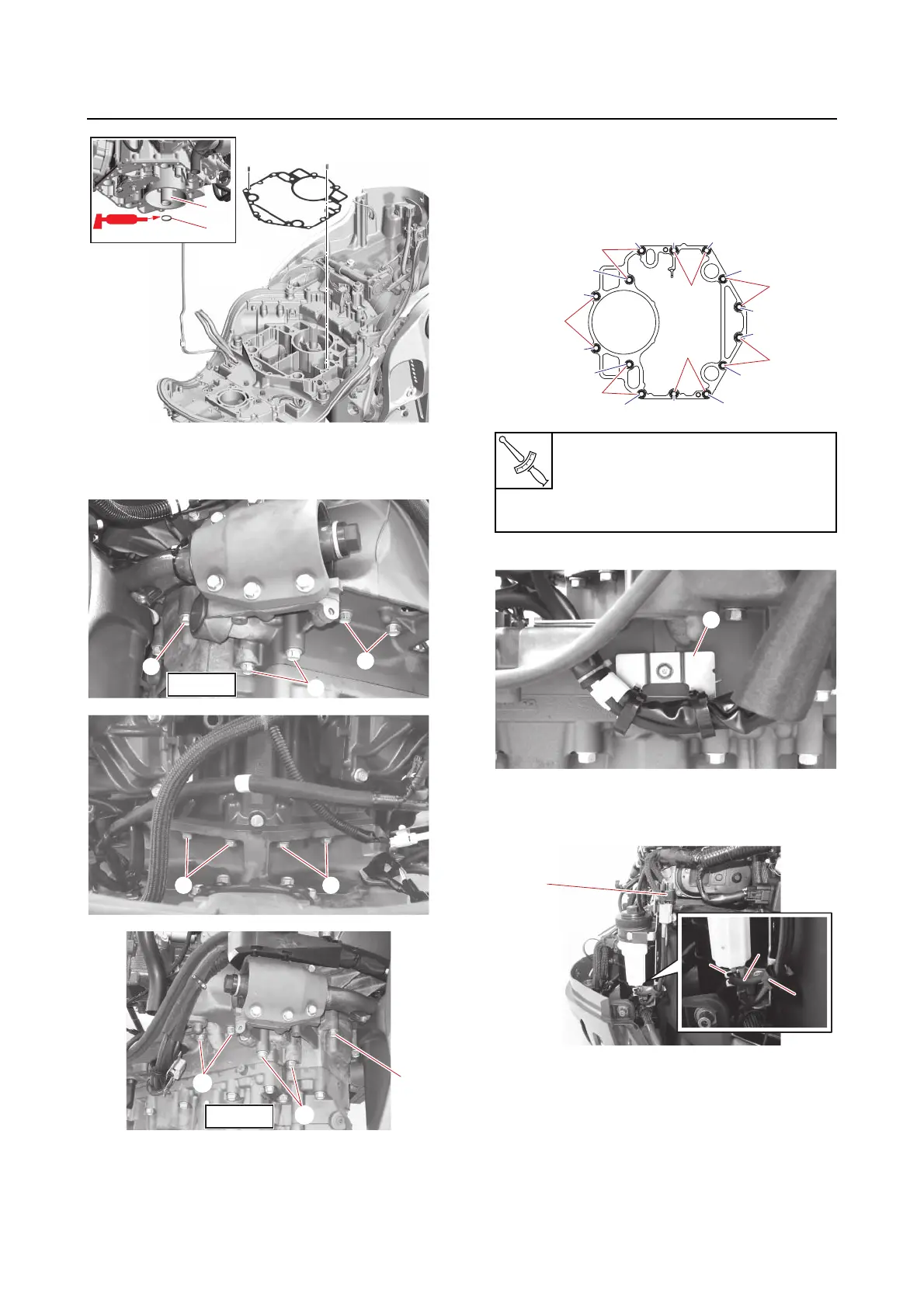
Power unit assembly
b. Install the power unit, and then tighten
the power unit mounting bolts “1”, “2”
and “3” temporarily.
c. Tighten the power unit mounting bolts
“1”, “2” and “3” to the specified
torques in 2 stages and in the order [1],
[2], and so on.
d. Install the bracket “1”
5. Install:
• PTT switch lead “1”
• Holders “2”, “3”
6. Connect:
• SPS lead coupler “1”
Power unit mounting bolt “1”, “2”,
“3”
1st: 42 N·m (4.2 kgf·m, 31 lb·ft)
2nd: 42 N·m (4.2 kgf·m, 31 lb·ft)
3
[2][25][2][25] [3][24][3][24]
[14][23][14][23]
[13][22][13][22]
[12][21][12][21]
[11][20][11][20]
[8][19][8][19][7][18][7][18][10][17][10][17]
[9][16][9][16]
[4][27][4][27]
[1][28][1][28]
[6][15][6][15]
[5][26][5][26]
2
2
1
3
1
1