Power unit assembly
7-19
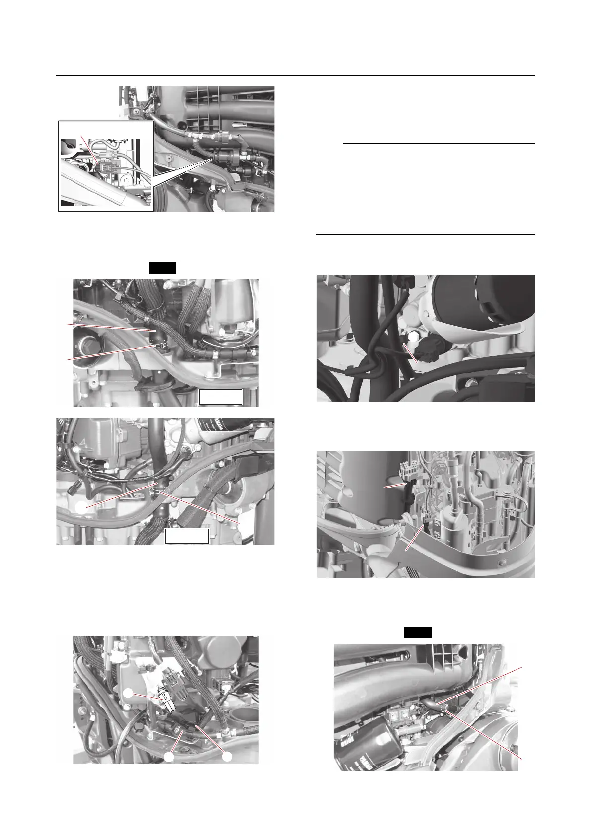
7. Connect:
• Cooling water hoses “1”, “2”
(to the joint)
•Plastic ties “3”
8. Connect:
• PTT sensor coupler “1”
• Fuel hose “2”
(to the holder bracket)
• Wire harness “3”
(to the holder bracket)
9. Install:
• SCU signal coupler (4 pins)
• SCU signal coupler (3 pins)
For single engine applications, connect the
SCU signal coupler (4 pins) to the wire har-
ness, and for multiple engine applications,
connect the coupler to the SCU communica-
tion lead (optional). See “Electrical component
and wire harness routing” (5-1).
10. Connect:
• SCU negative terminal “1”
11. Install:
• Shift actuator motor coupler “1”
• Main wire harness coupler “2”
12. Connect:
• Flushing hose “1”
(to the joint)
• Plastic tie “2”