7-20
Power unit assembly
13. Install:
• Isolator lead “1”
•Washer
(equipped with optional isolator lead)
• Positive battery cable “a”
• Negative battery cable “b”
When installing the battery cables, make sure
that the flushing hose is not pulled or twisted
and does not contact other parts.
14. Install (for multiple engine applications):
• SCU communication lead
•Plastic tie
See “Installing the SCU communication
lead” (3-15).
15. Install:
• Rigging grommet
• Rigging grommet holder
• Rigging grommet retainer
See “Installing the rigging grommet”
(3-13).
Route each harness through the proper hole in
the rigging grommet. See “Rigging grommet
description” (3-13).
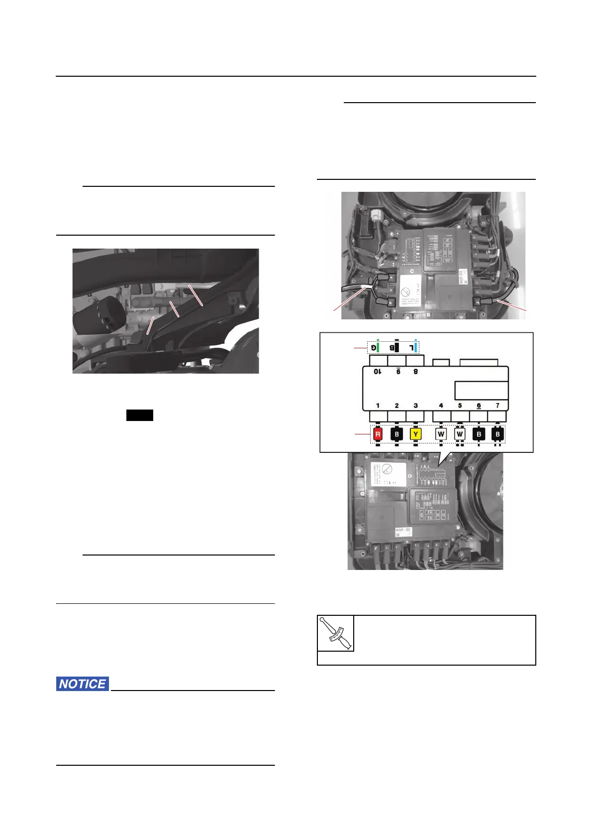
16. Install:
•Caps
• PTT motor lead “1”
• SCU positive lead “2”
When tightening the electrical manage-
ment box terminal nuts, do not exceed the
specified torque. Otherwise, the base of the
electrical management box could be dam-
aged.
• Route the PTT lead and SCU lead. See
“Electrical component and wire harness
routing” (5-1).
• Connect the specified leads to the terminals
of the electrical management box.
17. Install:
• Blowby hose guide
•Holders
• Blowby hoses
18. Install:
• Exhaust joint assembly
See “Installing the exhaust joint assem-
bly” (7-8).
a. Lead color
b. Tape color
Electrical management box termi-
nal nut
7.6 N·m (0.76 kgf·m, 5.6 lb·ft)