7-94
Cylinder block
• In the third tightening stage for the connect-
ing rod bolts “2”, mark the connecting rod
bolts and connecting rod cap with paint
marks “c”, and then tighten the bolts 90°
from the marks on the connecting rod cap.
• After tightening the connecting rod bolts “2”,
make sure that the crankshaft turns smooth-
ly.
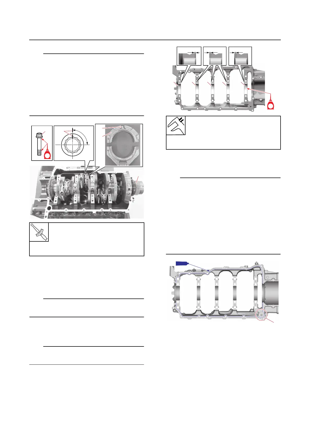
8. Install:
•Crankcase
a. Install the thrust bearings (crankcase
side).
Install each thrust bearing with its grooves fac-
ing outward.
b. Install the crankshaft journal bearings
(crankcase side) “1”.
Install the crankshaft journal bearings “1” in
their original positions.
c. Apply a thin, even layer of sealant onto
the mating surface of the crankcase.
• Do not apply any sealant to the crankshaft
journal bearings.
• When applying sealant to the portion “a” of
the mating surface, be careful not to apply
sealant to an area that will contact the O-
ring.
• Install the crankcase within 3 minutes after
applying the sealant. Tighten the crankcase
bolts to the specified torque within 15 min-
utes after applying the sealant.
d. Install a new O-ring, dowels, and the
crankcase, and then tighten the crank-
case bolts (M10) “1” to the specified
torques in 2 stages and in the order [1],
[2], and so on.
Connecting rod bolt “2”
1st: 13 N·m (1.3 kgf·m, 9.6 lb·ft)
2nd: 28 N·m (2.8 kgf·m, 21 lb·ft)
3rd: 90°
Distance “a”
0.65–1.25 mm (0.026–0.049 in)
Distance “b”
0.95–1.55 mm (0.037–0.061 in)