R5905948 /12 Event Master Devices336
EC-210 Overview
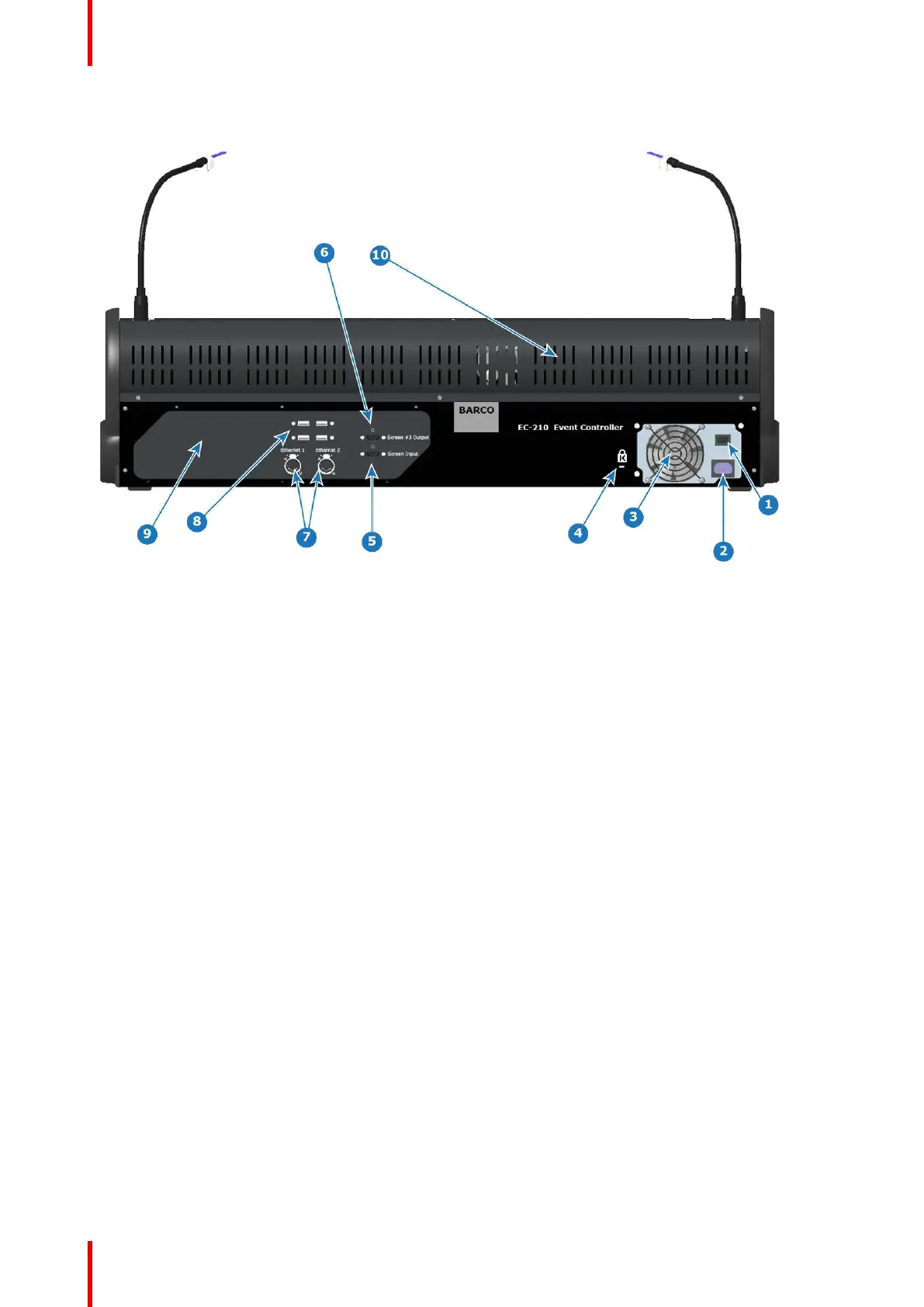
Image 10-8: EC-210 backside overview
1 Power switch
2 Power receptacle
3 PSU fan outlet, not to be blocked
4 Kensington Lock attachment point
5 HDMI input connector
6 HDMI output connector
7 2x Ethernet RJ45 network connectors
8 4x USB A connectors for USB peripherals, such as mouse
and keyboard
9 Rear I/O plate
10 Red effects light (located behind rear vent holes)
10.8 Use of color
General
The unit has several colored buttons and LED indicators which support the user by indicating selections and
possible actions.
Button color
• Blue buttons indicate the Freeze function.
• Green buttons indicate a layer selection or an action to a layer selection.
• Red buttons always indicate actions that can affect Program.
• Yellow is used for the Save function.
• Black is neutral.
LED Color in buttons
• Blue indicates selected destination buttons.
• Green indicates that the layer on preview is selected (Normal).
• Green can also indicate that the button’s function has an opposite function or other mode.
• Red indicates that the layer on program is selected (Live or Unlocked Program).
• Red can also indicate that the button’s function is selected / active, like T-Bar Disable.
Controller Orientation