R5905948 /12 Event Master Devices 285
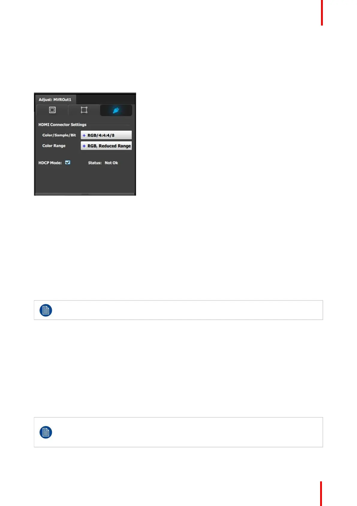
7. [Connector tab] Select Color space and Sample bit depth available as reported from the EDID of the Device.
8. [Connector tab] Change Connector capacity as long as the connector is not included in a Destination.
9. [Connector tab] Select HDCP Mode On or Off.
The default for all outputs is Off. To turn On the HDCP Mode, click on the empty checkbox. When the
checkbox displays a check mark, HDCP Mode is On. HDCP Mode is not applicable to SDI outputs.
Image 7-3: Adjust MVR panel—Connector
7.14 Configuration Menu > Add Screen
Destinations & Layers
General
In this procedure, you will Add Screen Destinations from the defined outputs.
Prerequisite
• Ensure that you are familiar with the Configuration Menu. For details on this menu, please refer to
chapter “Configuration Menu”, page 109
If more than one Destination is utilized, repeat the below steps until all Destinations are added.
Add Screen Destinations
1. Click on the Destination tab to define destinations for the configured outputs.
2. From the diagram area click on the output that you want to be part of the new screen destination.
3. Click on the +Add Screen Destination blue button to assign the output to a new screen destination.
4. When the destination is created a green rectangle, with a label at the bottom of it, appears next to the unit
diagram.
5. If more than one output is to be assigned to the destination, such as a wide-screen projection blend, drag and
drop any additional outputs into the destination rectangle. You will observe that the destination size is
automatically updated as new outputs are added to the destination.
An EMP allows only a certain mix of Screen (Program) Destinations and AUX Destinations. All
Outputs can be AUX Destinations, or all Outputs can be assigned to Screen Destinations. Screen
Destination sizes are determined by the available amount of pixel canvas, not by the number of
Outputs assigned to a Screen Destination.
System Setup