R5905948 /12 Event Master Devices80
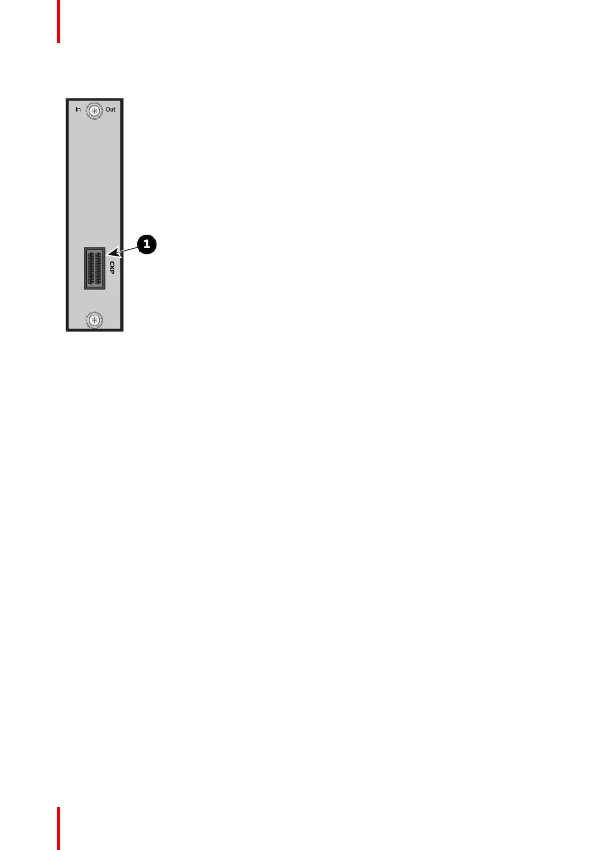
The figure below illustrates the CXP I/O card's rear panel connector:
Image 4-20
1 CXP connector
Features
• Adds the ability of linked Event Master systems to extend up to eight links of input or output (slot
dependent) to an EX chassis
• Uses CXP cables for connectors
• Can be converted to MTP fiber optic cable up to 300m
• 1x CXP (120G) connector
Specifications
• CXP specification
CXP link-cable communication support
• Communication can enabled or disabled per CXP link connector.
• The maximum number communication links via CXP link cable in a system is six (6).
• The unit ID of the EX must be unique.
• The static IP address—if used—of the EX must be unique.
CXP link-cable communication limitations
• An EX expansion box connected to an E2/S3 by a CXP link card must be connected as a slave only.
• Users will not be able to update the Unit ID of the EX via CXP communication.
The unit ID must be updated via Ethernet communication.
• Users will not be able to daisy chain EXs when the EX connected to E2 or S3 has CXP communication
enabled.
• Users will not be able to use the CXP I/O card with CXP communication enabled on the S3 when the
system is an E2-to-S3 configuration.
The CXP I/O card on any slave units must use Ethernet communication.
• EX web app will not be accessible.
Hardware orientation