A
B
C
D
E
F
G
H
L
M
N
P
section
P 3
52 1098/1098S - M.Y. 2007 - edition 00
Electric system
3 - Electric starting system
Notes
The references of the elements shown below are to be found in the Wiring diagram” in Sect. P 1.
Electric starting system
The key components of the electric starting system are a contactor (6) and a starter motor (5) fed by the battery (7).
The engine starting strategy is managed entirely by the engine ECU (34), which monitors the following inputs:
- Engine Stop switch on right-hand handlebar switch (1)
- Engine starter switch on right-hand handlebar switch (1)
- Neutral sensor (31)
- Sidestand sensor (29)
- Clutch microswitch (36)
When these inputs are combined in the required manner, the engine control unit (34) enables engine starting.
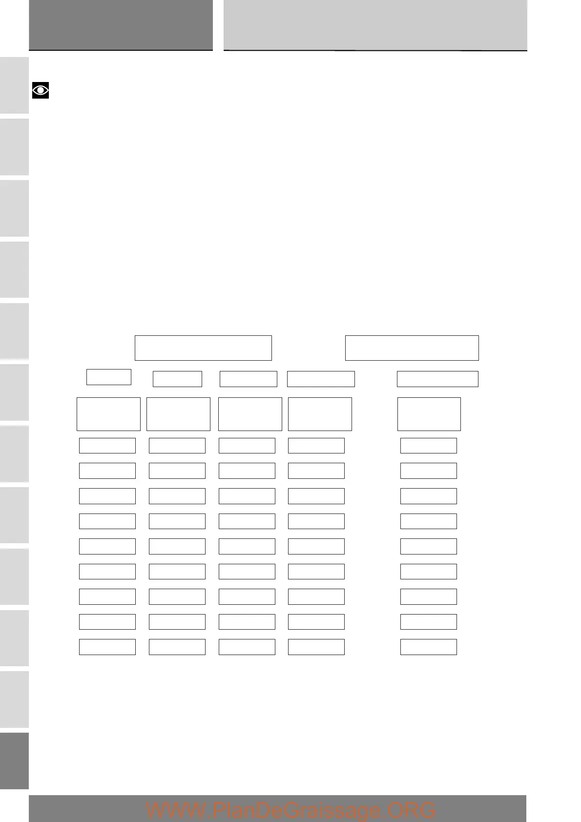
The table lists possible engine starting combinations.
In accordance with the status of specific engine control unit inputs and the indications given in the table, the control unit enables
operation of the starter motor (ON status) when the START button is pressed.
X = generic status of neutral sensor, clutch, and sidestand.
Safety device functions table
ECU INPUTS
ECU OUTPUTS
NEUTRAL
CLUTCH
STAND
ENGINE STOP
STARTER MOTOR
ECU
ENGINE 14
PIN
ECU
BODY 33
PIN
ECU
BODY 38
PIN
ECU
BODY 27
PIN
ECU
BODY 1
PIN
X
NEUTRAL PULLED DOWN
DOWN
DOWN
DOWN
UP
UP
UP
UP
RELEASED
RELEASED
RELEASED
RELEASED
PULLED
PULLED
PULLED
NEUTRAL
GEAR
GEAR
GEAR
GEAR
NEUTRAL
NEUTRAL
X X OFF
ON ON
ON
ON
ON
ON
ON
ON
ON
ON
ON
ON
ON
OFF
OFF
OFF
OFF
1
 Loading...