A
B
C
D
E
F
G
H
L
M
N
P
section
P 5
68 1098/1098S - M.Y. 2007 - edition 00
Electric system
The colours mentioned in the following descriptions refer to the colours of the wires from the switch and not to the colours of
the wires of the main electrical system.
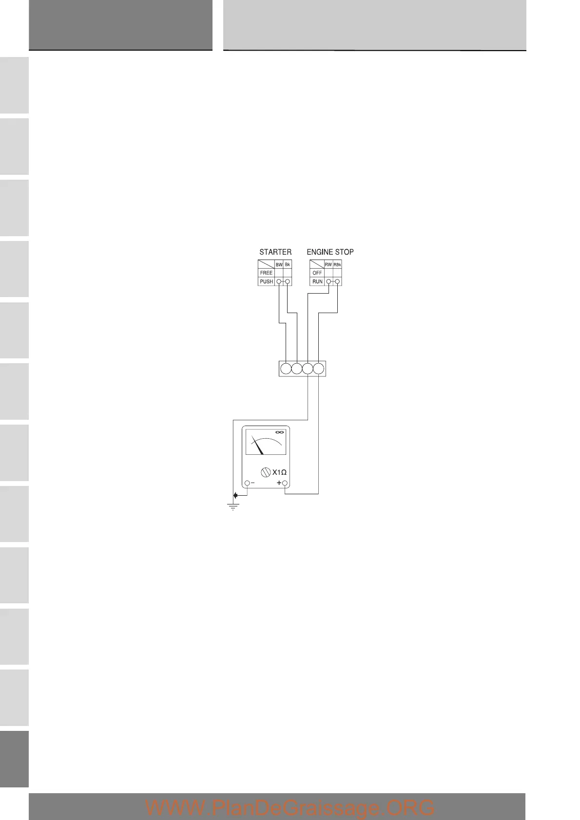
ENGINE STOP button
Using a multimeter, check for continuity between the Red/Black and Red/White wires (see Sect. P 9, Diagnostic instruments for
information on the operation of the multimeter). When the button is in RUN position, there should be electrical continuity
between the two wires. When the button is in the OFF position, there should be no electrical continuity between the two wires.
If these conditions are not met, the ENGINE STOP switch is not working correctly and must be renewed. The colours indicated
above refer to the colour of wires coming from the switch and not to the colour of wires of the main electrical system.
STARTER switch
Proceed as described for the engine STOP button and check for continuity between the Blue/White and Black wires when the
STARTER button is pressed (see Sect. P 9, Diagnostic instruments concerning operation of the multimeter). If there is no
continuity, the STARTER button is faulty and must be renewed. The colours indicated above refer to the colour of wires coming
from the switch and not to the colour of wires of the main electrical system.
Refit the left-hand handlebar switch and tighten the screws (1) to the specified torque (Sect. C 3, Frame torque settings).