Chapter 3 ’Web User Graphical Interface’ — Operating Instructions (Tutorial)
154 Electra VS
-
Version 05.10
User Manual - Rev. A
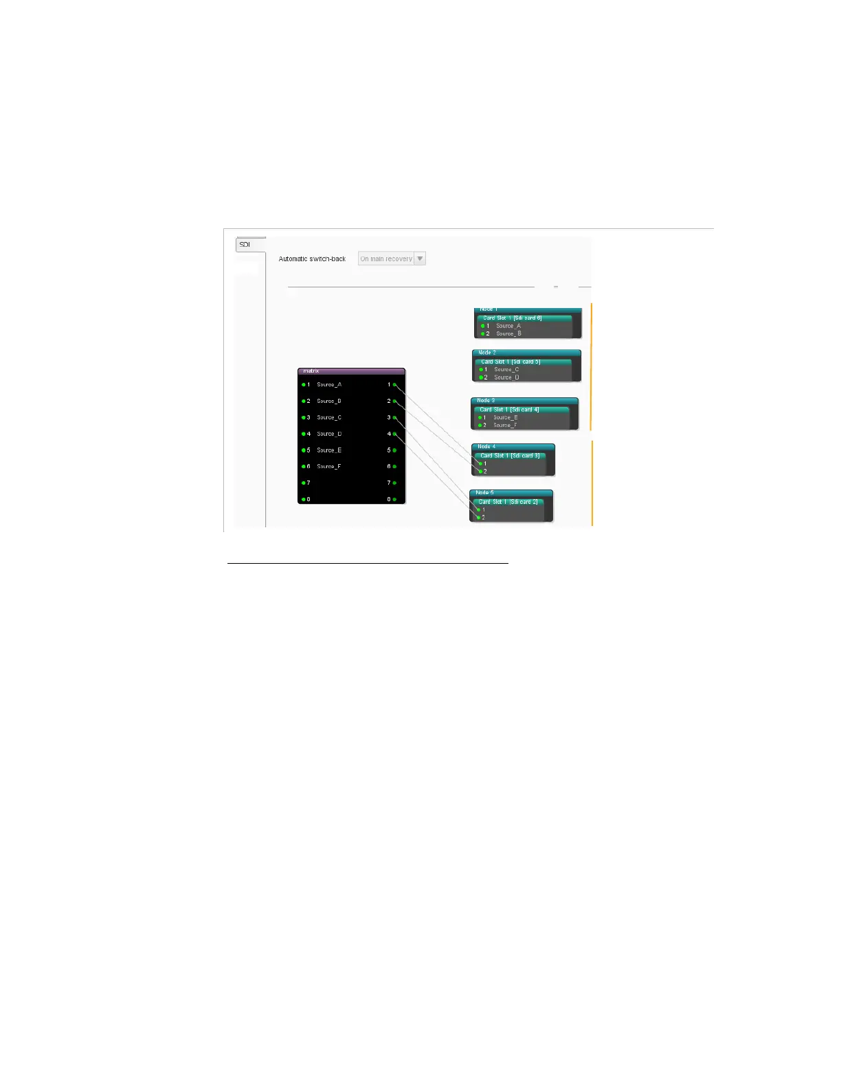
To connect a matrix output to a Node, click an output of the matrix, hold
the mouse and drag it over an input node of an SDI board. A link is
created.
The figure below shows an example of a redundant topology example.
Figure 3-107. Linking the matrix to the node inputs (Redundant topology)
Configuring the Crosspoints of the Matrix
By default, the crosspoints are dynamic and are managed by the Electra
VS. However it is also possible to create static crosspoints.
To create a static crosspoint, click an input of the matrix, hold the
mouse and drag it over an output of the matrix. A static crosspoint is
created. The static crosspoints are blue.
To delete a static crosspoint, right-click the crosspoint and select
remove link
.
The figure below shows a redundancy topology with static crosspoints in
the matrix.
Nominal nodes
Redundant nodes