7½ Digit Graphical Sampling Multimeter Reference Manual Section 2:
DMM7510-901-01 Rev. B / May 2015 2-17
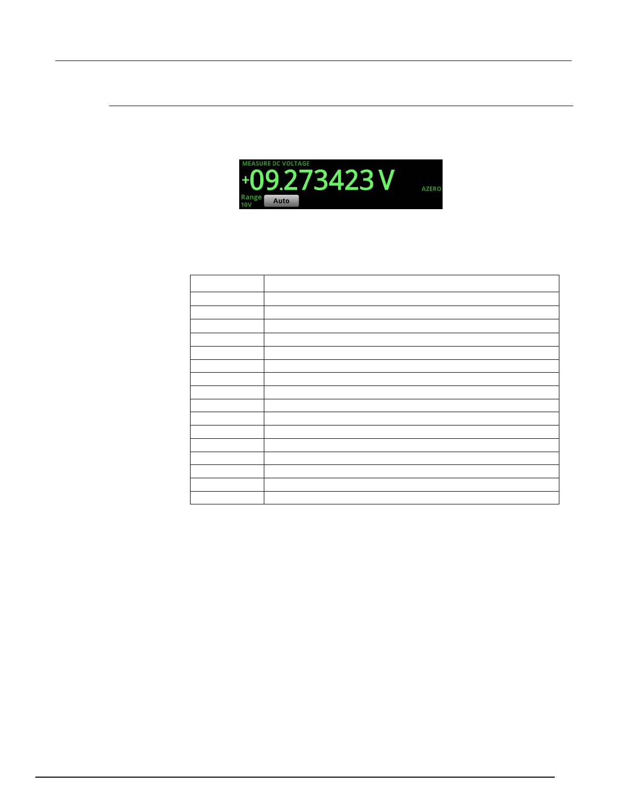
Measure view area
The Measure view area of the Home screen displays the value of the present measurement and other
measurement information.
Figure 13: Measure view area of the home screen
The Range button on the lower left displays the presently selected measure range. Select the button
to change the range.
The indicators on the right edge of the Measure view area show any measure settings that affect the
displayed measurement value. The indicators and what they mean are defined in the following table.
Indicator Meaning
Ω
Input impedance is set to 10 M
Ω
AC signal coupling is enabled
Ω
Input impedance is set to automatic
Instrument automatically retrieves reference values
DC signal coupling is enabled
Dry circuit ohms is enabled
A filter is applied to the measurement
Limit test one is enabled and measurement failed
Limit test one is enabled and measurement passed
Limit test two is enabled and measurement failed
Limit test two is enabled and measurement passed
A percent, mx+b, or reciprocal calculation is applied
Offset compensation is enabled
Open lead detection is enabled
Relative offset is applied
The thermocouple reference junction is simulated
 Loading...


