Acquisition and waveform setup
R&S
®
RTE
188User Manual 1326.1032.02 ─ 20
If a Rohde & Schwarz modular probe is connected, the offset of the selected probe
mode is used. For example, in CM mode, the offset is the common mode offset.
By default, the horizontal grid axis remains in the center when the offset is changed. To
shift the axis together with the waveform, disable Keep Y-grid fixed in "Display > Dia-
gram Layout".
Remote command:
CHANnel<m>:OFFSet on page 1119
Bandwith
Selects the bandwidth limit.
The specified bandwidth indicates the range of frequencies that the instrument can
acquire and display accurately with less than 3dB attenuation. The probe has also a
limited bandwidth and thus affects the resulting system bandwidth.
See also: Chapter 5.1.1.3, "Bandwidth", on page 168
"Full"
At full bandwidth, all frequencies in the specified range are acquired
and displayed. Full bandwidth is used for most applications.
"20 MHz, 200 MHz"
Frequencies above the selected limit are removed to reduce noise at
different levels.
Remote command:
CHANnel<m>:BANDwidth on page 1120
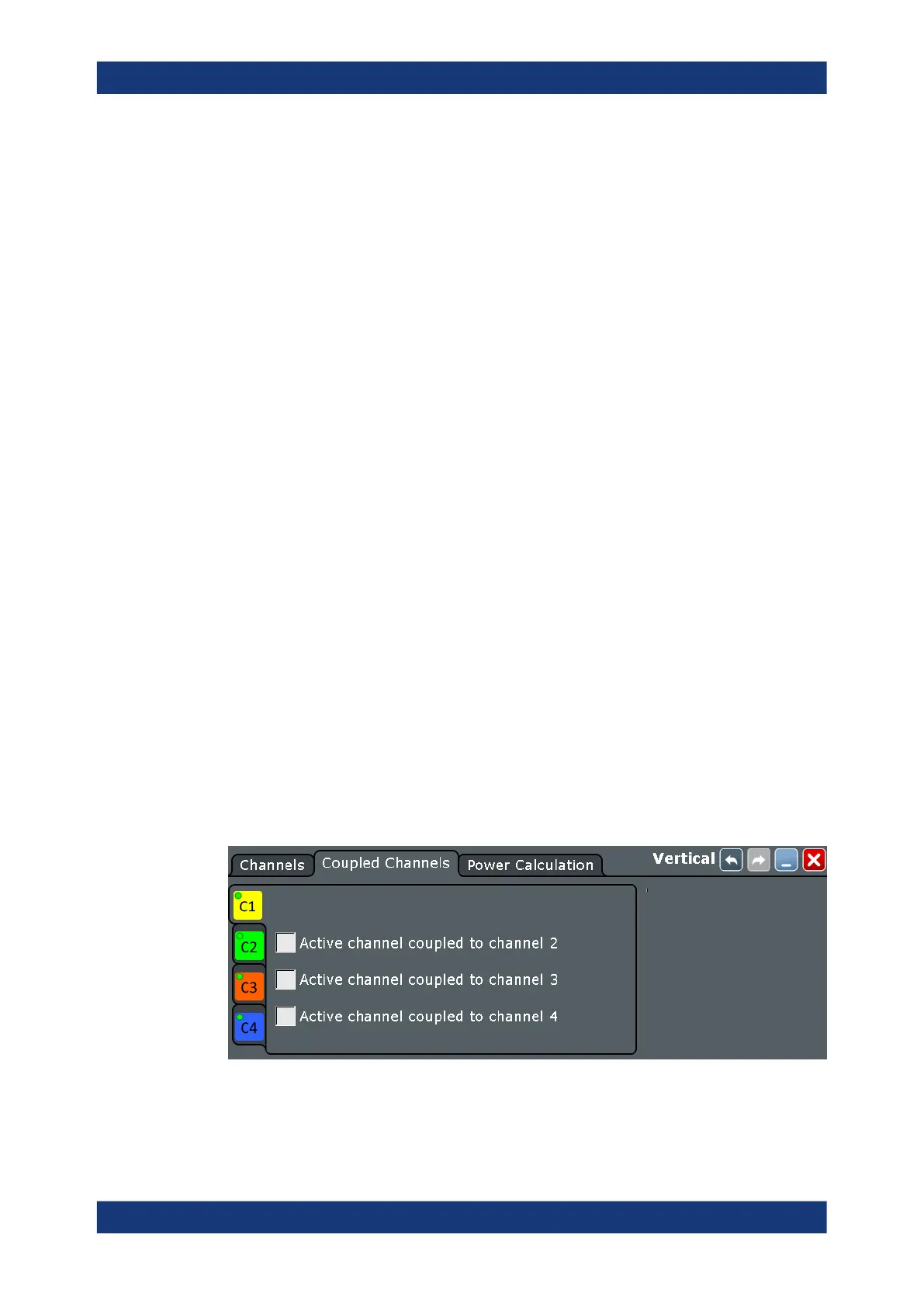
5.3.2 Coupled channels
Access: "Vertical" menu > "Coupled Channels"
Channel coupling sets the vertical settings of the coupled channels to the values of the
active channel. If you want to have the same vertical settings for two or more channels,
you can set them at once by coupling these channels.
Channel coupling affects all vertical settings that are adjusted in the "Channels" tab:
vertical scale, position, offset, bandwidth, coupling, and ground.
Remote command:
●
CHANnel<m>:CPLing on page 1120
Vertical settings

 Loading...


