Measurements
R&S
®
RTE
354User Manual 1326.1032.02 ─ 20
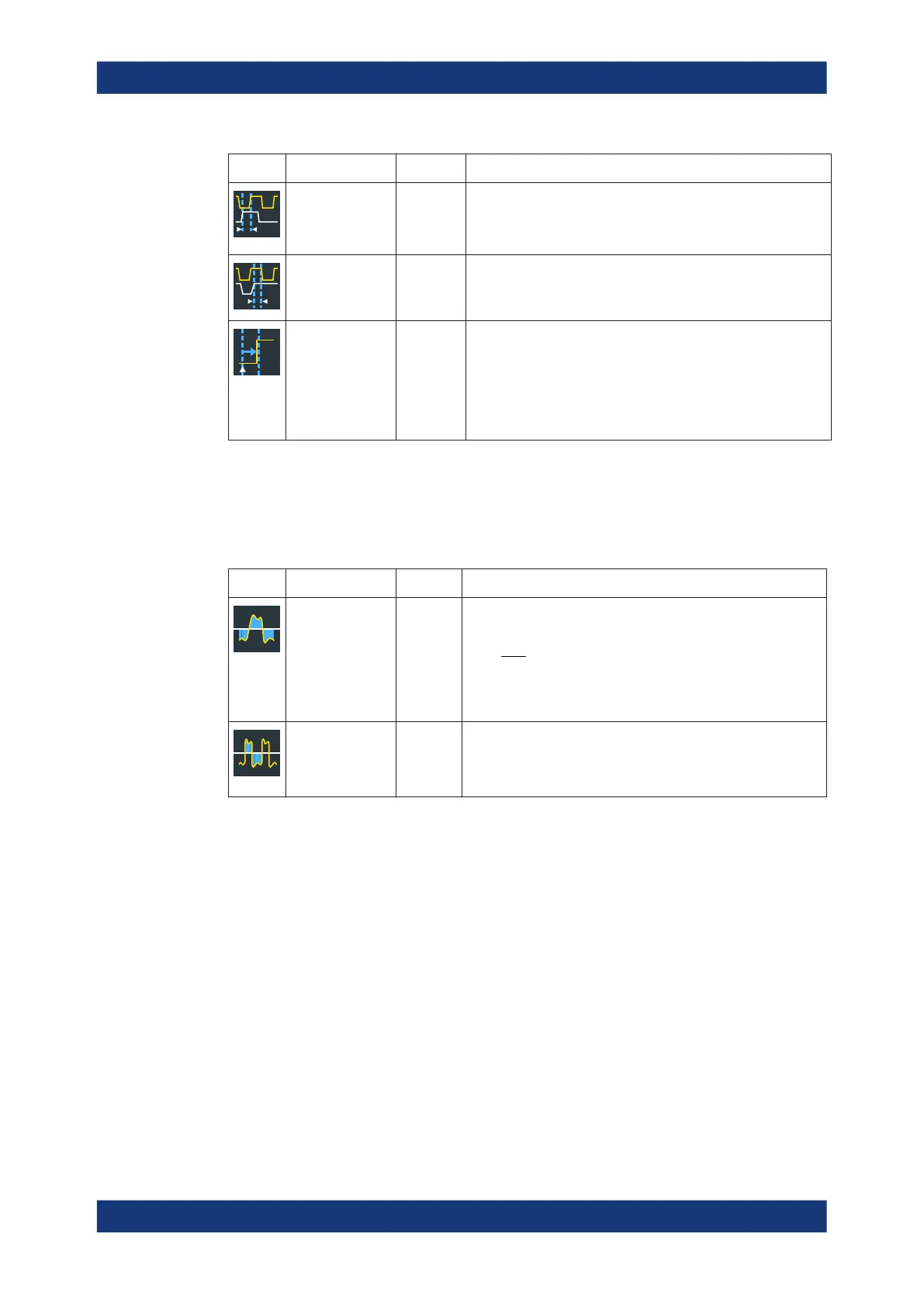
Meas. type Symbol Description/Result
Setup
Hold
Setup/Hold time
T
Setup
and
T
Hold
Setup and Hold time measurement with positive and/or negative
clock edge.
See: "Setup/Hold measurement settings" on page 357
Setup/Hold ratio T
Setup
/
(T
S
etup
+
T
Hold
)
Setup/Hold ratio measurement with positive and/or negative
clock edge.
See: "Setup/Hold measurement settings" on page 357
Delay to trigger
Time between the trigger event and a following signal slope.
High accuracy even if the trigger event is outside the acquisition
data.
See:
●
"Delay to trigger measurement settings" on page 359
●
Chapter 8.2.5.3, "Measuring the delay to trigger",
on page 360
Area measurements
Access: "Meas" menu > "Setup" > "Amp/Time" category
Area measurements are voltage over time measurements.
Table 8-3: Area measurement types
Meas. type Symbol Description/Result
Area A
Ref
Area between the waveform and a reference level ("Area level",
X
Ref
).
Eval
N
i
Ref
Eval
Eval
Ref
Xix
N
T
A
1
)(
T
Eval
: Evaluation time, time of a full waveform or limited by a
gate
Cycle area A
RefCyc
Area between the waveform and a reference level ("Area level")
measured for one period, see also "Area" measurement. The
measurement requires at least one complete period of a trig-
gered signal. Multiple measurements are possible.
Counting
Access: "Meas" menu > "Setup" > "Amp/Time" category
Automatic measurements

 Loading...


