12713020-003-2 Revision F.01 – January 2007 SSU-2000 Technical Reference 337
Chapter 7 Connector Pinouts
Signal Names and Definitions
Communication Interfaces
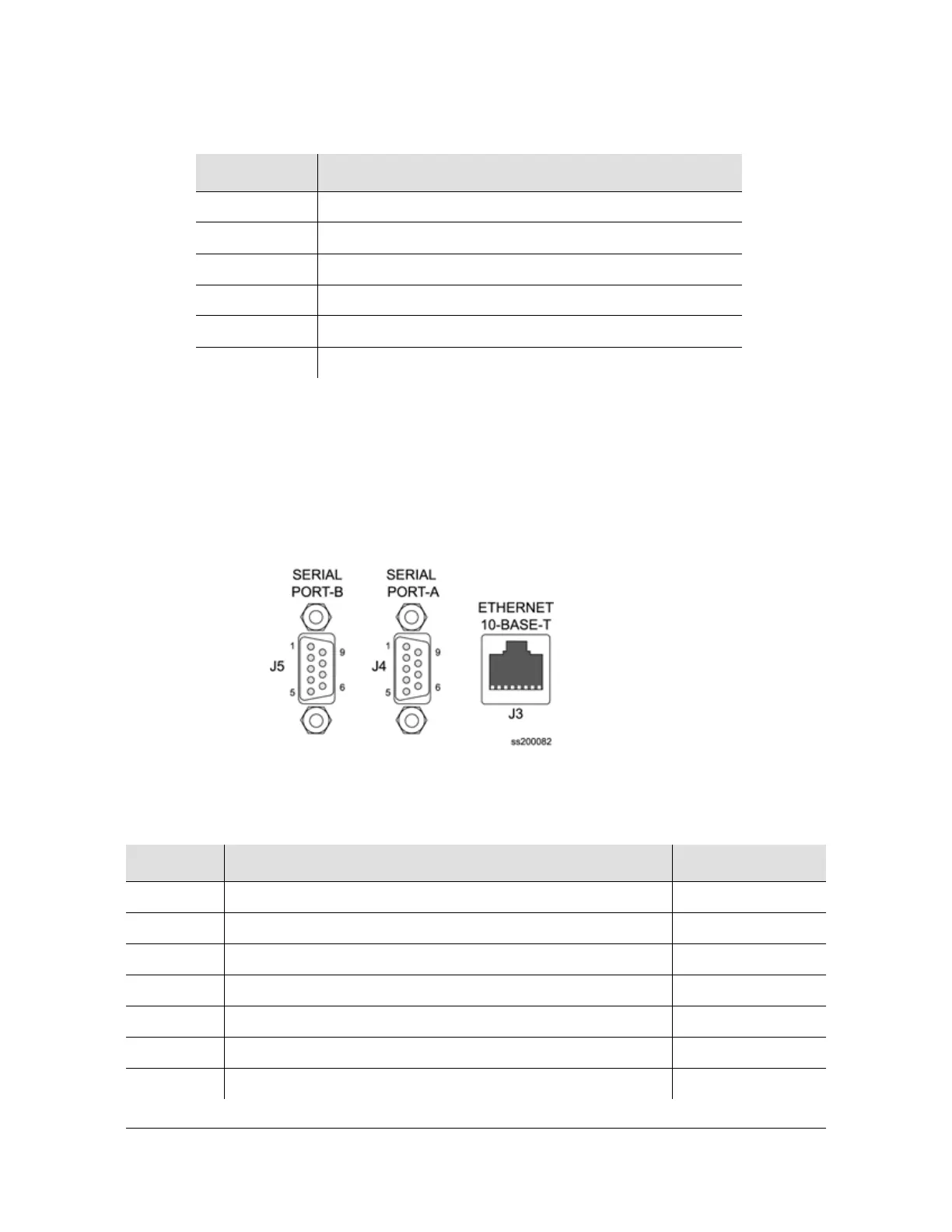
Figure 7-3 shows the communications interfaces on the rear panel of the
SSU-2000. Table 7-2 describes the signal names, definitions, and pinouts of
Communications connectors.
Figure 7-3. Communications Interface Pinout
Table 7-1. Signal Names and Definitions for Power and Ground
Name Description
APWR –48V from Power Bus A
ARTN –48V Return from Power Bus A
BPWR –48V from Power Bus B
BRTN –48V Return from Power Bus B
LG Logic Ground, Return for Non-Isolated Signals
FG Frame Ground Safety Ground for Shelf
Table 7-2. Pinouts of Communications Interfaces
Name Description Connector–Pin
DCD-A Serial Port A, Data Carrier Detect Control Line J4-1
DSR-A Serial Port A, Data Set Ready Control Line J4-6
RXD-A Serial Port A, Received Data J4-2
RTS-A Serial Port A, Request to Send Control Line J4-7
TXD-A Serial Port A, Transmitted Data J4-3
CTS-A Serial Port A, Clear to Send Control Line J4-8
DTR-A Serial Port A, Data Terminal Ready Control Line J4-4

 Loading...