12713020-003-2 Revision F.01 – January 2007 SSU-2000 Technical Reference 339
Chapter 7 Connector Pinouts
Signal Names and Definitions
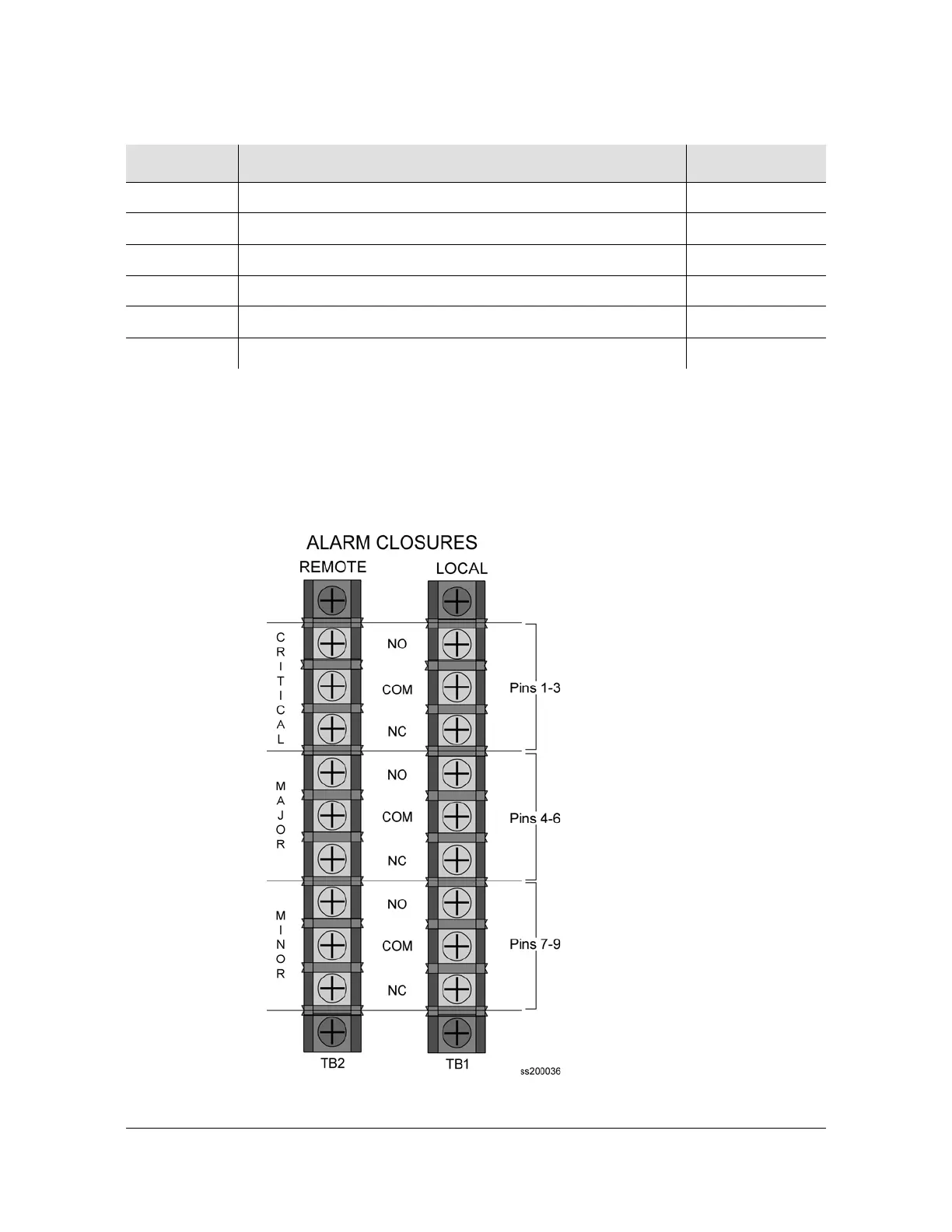
Alarm Contact Closures
Figure 7-5 illustrates the alarm closure connectors on the rear panel of the
SSU-2000 chassis. Table 7-4 outlines signal names, definitions, and locations of
alarm contact closures.
Figure 7-5. Alarm Connector Pinout
LO-B+ Local Oscillator B, Positive Side of Signal J2-A (Ctr)
LO-B- Local Oscillator B, Negative Side of Signal J2-B (Shld)
ANT-A Antenna A, Center Conductor (Received Signal & Ant. Power) J6-A (Ctr)
ANT-A-RTN Antenna A, Return J6-B (Shld)
ANT-B Antenna B, Center Conductor (Received Signal & Ant. Power) J7-A (Ctr)
ANT-B-RTN Antenna A, Return J7-B (Shld)
Table 7-3. Signal Names and Locations of Local OSC and Antennas (Continued)
Name Description Connector–Pin

 Loading...