12713020-003-2 Revision F.01 – January 2007 SSU-2000 Technical Reference 345
Chapter 7 Connector Pinouts
Shelf Module Slot Addressing and Size Assignments
Shelf Module Slot Addressing and Size Assignments
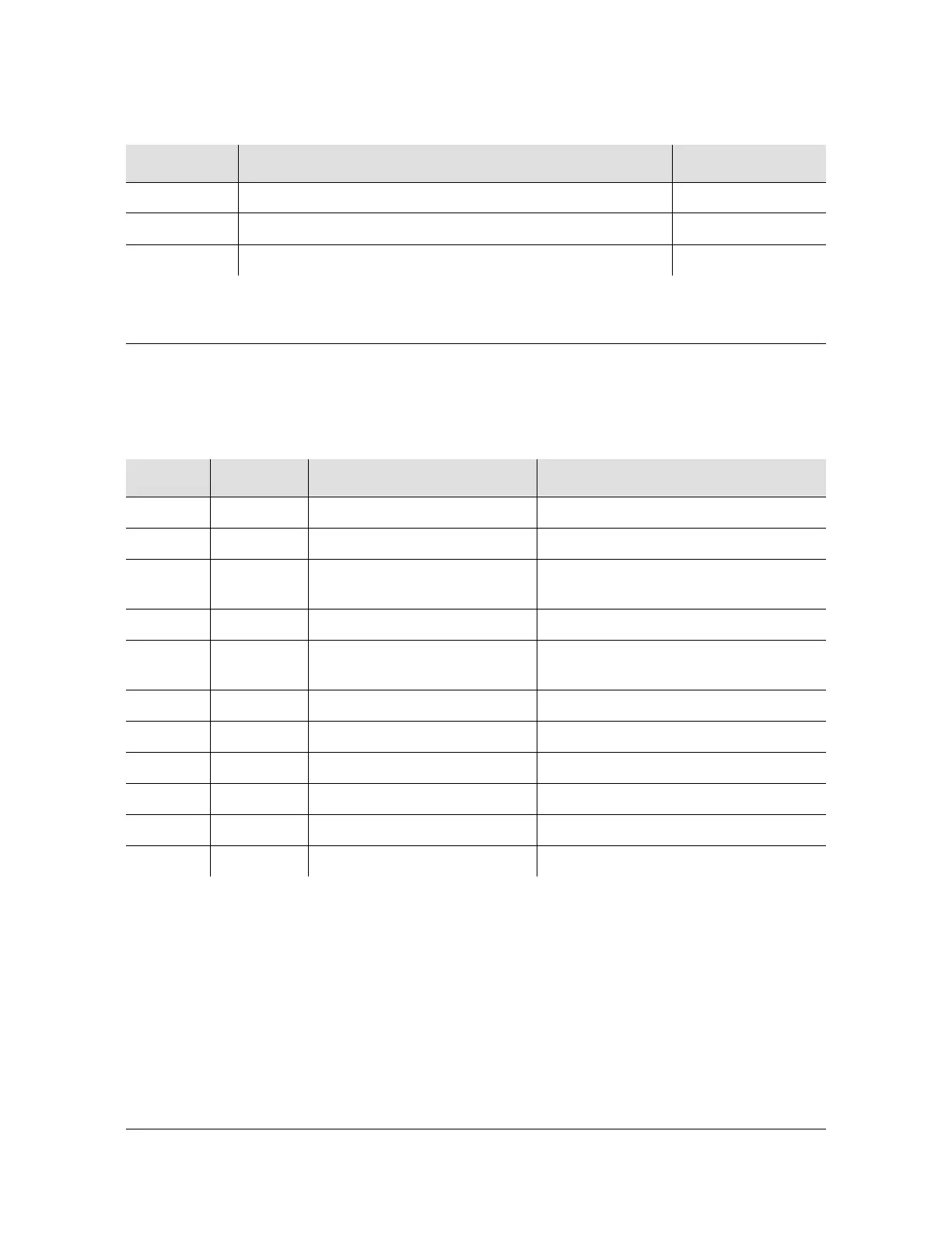
Table 7-8 outlines the shelf module slot addressing and size assignments.
ORING 19 Ring Connection of Output Signal # 19 47
OTIP 20 Tip Connection of Output Signal # 20 24
ORING 20 Ring Connection of Output Signal # 20 49
Table 7-8. Shelf Module Slot Addressing and Size Assignments
Slot-A Address Module Types Comments
1 1 Clock Clock A
2 2 Com Communications
3 3 I/O or Receiver Input, non-redundant Output, or a GPS
Receiver module
4 4 I/O, Output Pair A Input or Output, paired with 5
5 5 I/O, Output Pair A or Receiver Input, Output, paired with 4, or a GPS
Receiver module
6, 7 6, 7 I/O, Output Pair B Inputs or paired Output modules
8, 9 8, 9 I/O, Output Pair C Inputs or paired Output modules
10, 11 10, 11 I/O, Output Pair D Inputs or paired Outputs modules
12 - 15 I/O, Extras Reserved for future I/O
12 17 Clock Clock B
0 All Addresses all modules in the Shelf
Table 7-7. 50 Pin Connector Input/Output Signal Names and Location (Continued)
Name Description Connector Pin #

 Loading...