Chapter 7 Connector Pinouts
Signal Names and Definitions
338 SSU-2000 Technical Reference 12713020-003-2 Revision F.01 – January 2007
Local OSC and Antennas
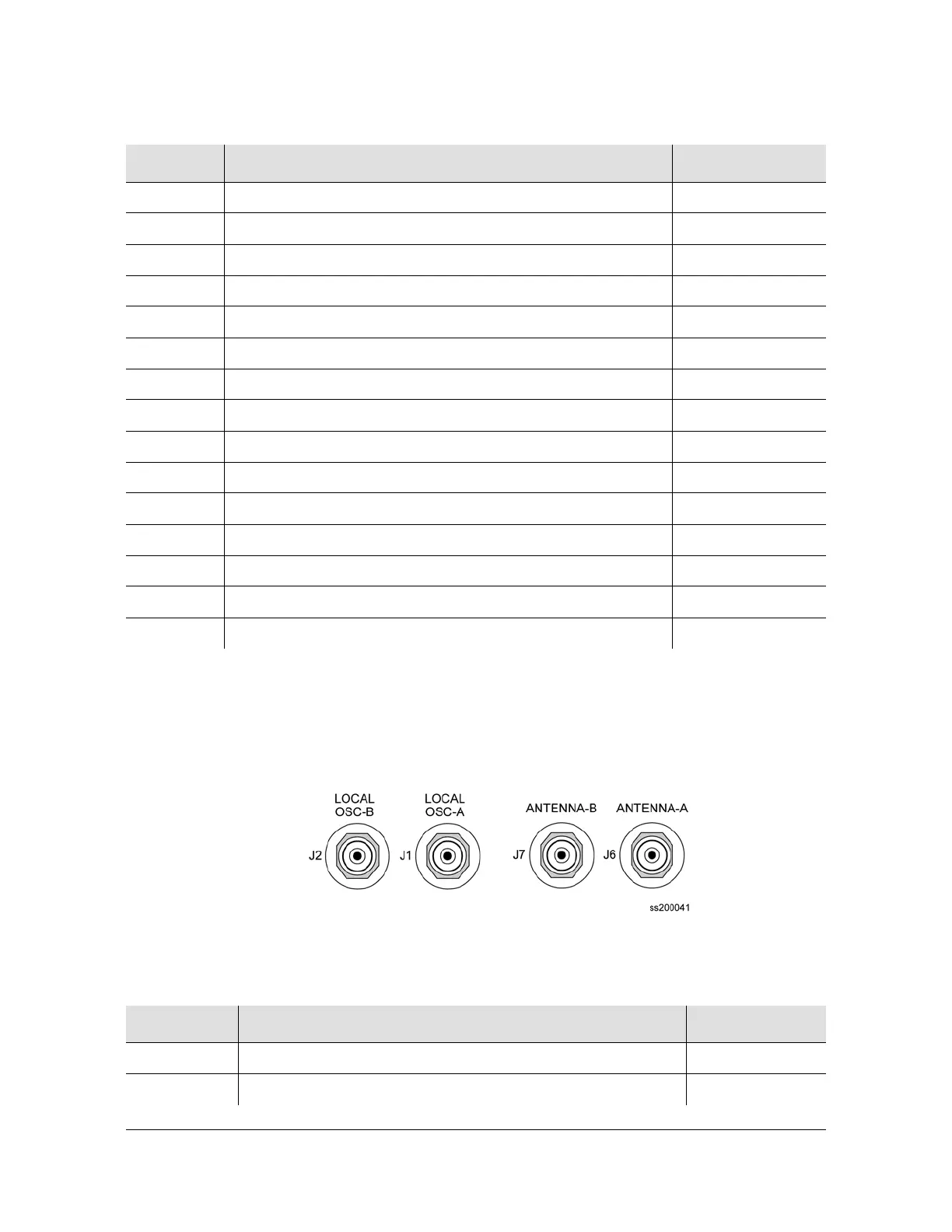
Figure 7-4 illustrates the location of the oscillator and antenna connectors. Table 7-3
describes the pinouts of local Oscillators and antenna connectors.
Figure 7-4. Local Oscillator and Antenna Connectors
RI-A Serial Port A, Ring Indicator Control Line J4-9
RTN-A Serial Port A, Signal Return J4-5
DCD-B Serial Port B, Data Carrier Detect Control Line J5-1
DSR-B Serial Port B, Data Set Ready Control Line J5-6
RXD-B Serial Port B, Received Data J5-2
RTS-B Serial Port B, Request to Send Control Line J5-7
TXD-B Serial Port B, Transmitted Data J5-3
CTS-B Serial Port B, Clear to Send Control Line J5-8
DTR-B Serial Port B, Data Terminal Ready Control Line J5-4
RI-B Serial Port B, Ring Indicator Control Line J5-9
RTN-B Serial Port B, Signal Return J5-5
TX+ Ethernet 10-Base-T, Positive Side of Transmitted Data J3-1
TX- Ethernet 10-Base-T, Negative Side of Transmitted Data J3-2
RX+ Ethernet 10-Base-T, Positive Side of Received Data J3-3
RX- Ethernet 10-Base-T, Negative Side of Received Data J3-6
Table 7-3. Signal Names and Locations of Local OSC and Antennas
Name Description Connector–Pin
LO-A+ Local Oscillator A, Positive Side of Signal J1-A (Ctr)
LO-A- Local Oscillator A, Negative Side of Signal J1-B (Shld)
Table 7-2. Pinouts of Communications Interfaces (Continued)
Name Description Connector–Pin

 Loading...