Chapter 7 Connector Pinouts
Signal Names and Definitions
342 SSU-2000 Technical Reference 12713020-003-2 Revision F.01 – January 2007
50-Pin Connector Input and Output Signals
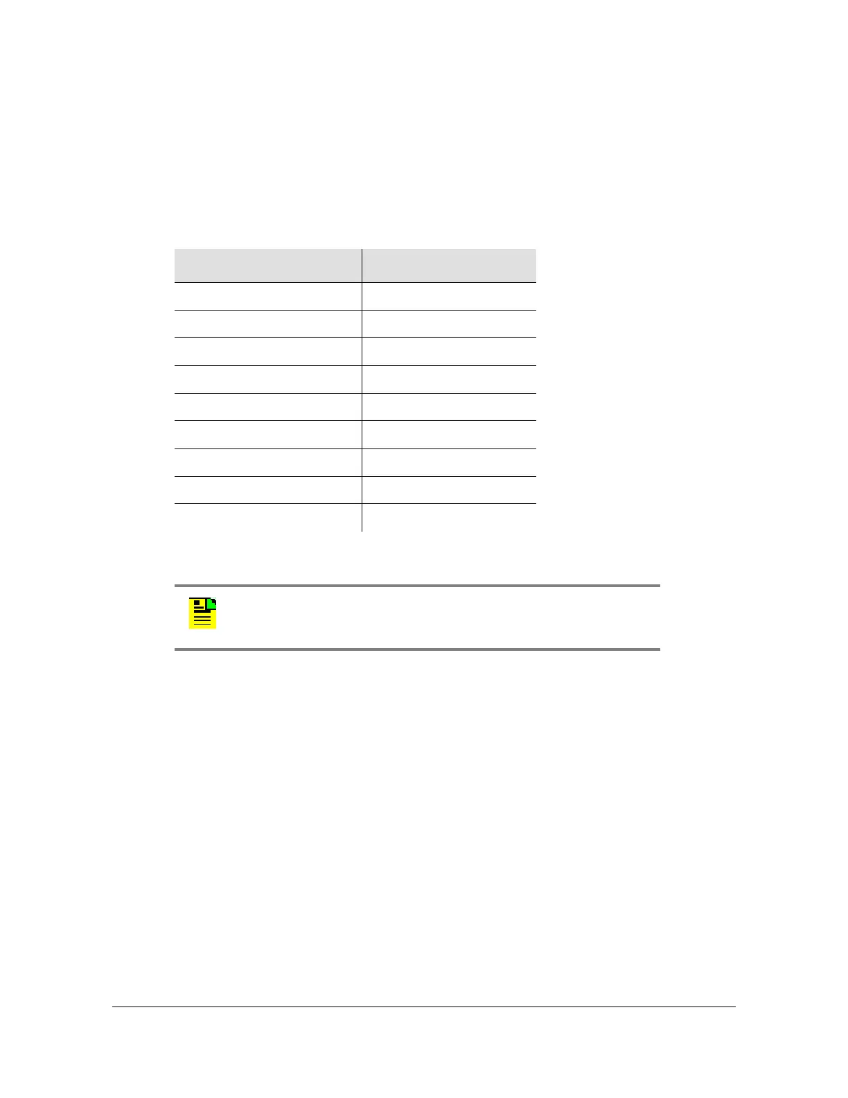
Table D-6 corresponds the 50-pin I/O signal connectors to the appropriate I/O slot
location. The connectors J10 through J18 are hard wired through the backplane to
I/O slots A3 through A11.
Table 7-7 outlines input and output signal definitions on connectors J10 through
J18, which are the nine 50-pin connectors located on the rear panel of the
SSU-2000 Main shelf.
Table 7-6. I/O Slot Locations
Rear Panel Connector I/O Slot Location
J10 A3
J11 A4
J12 A5
J13 A6
J14 A7
J15 A8
J16 A9
J17 A10
J18 A11
Note: The pin assignments for J10 through J18 are identical. The
pin assignments outlined in Table D-7 refer to all nine of these
connectors.

 Loading...