Service Parts Disassembly
Phaser 3610, WorkCentre 3615 Service Manual 4-83
Replacement
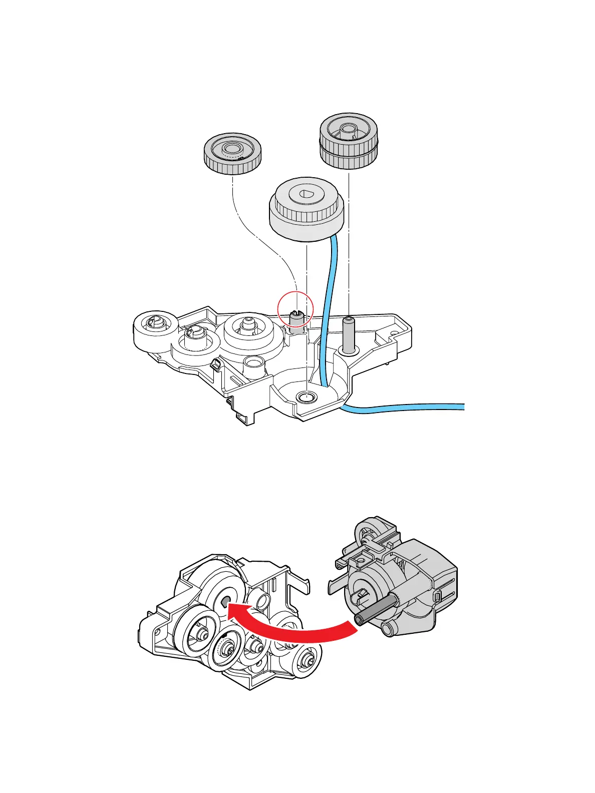
1. Component placement in the Exit Output Drive Assembly is shown below. (Figure 1)
Figure 1
2. Insert the ground strap between the LVPS and frame. Also, when installing the Exit Output Drive
Assembly, fit the D-shaped shaft of the Exit Invert Drive Assembly into the D-shaped hole of the
exit clutch. (Figure 1)
Figure 2
s3610-052
s3610-053
 Loading...