Upper case assembly and mount
9-23
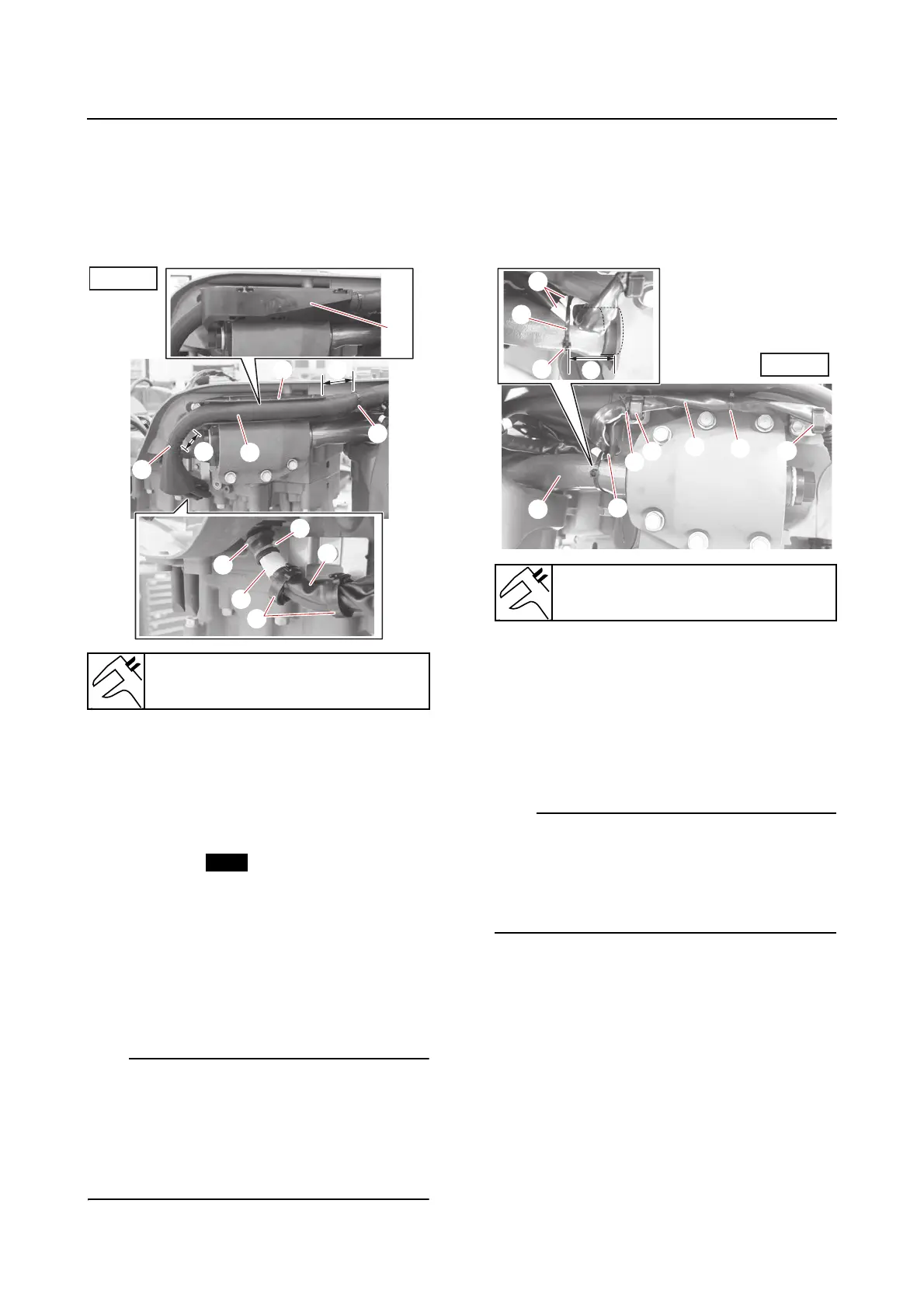
d. Fasten the grommet “5” and SCU lead
“2” using a new plastic tie “6” so that
the lower edge of the grommet over-
laps the white tape “b” on the lead.
e. Fasten the SCU lead “2” using the
holders “7”.
6. Install:
• PTT motor lead
•Holders
• PTT sensor lead
• Protective tube
• Corrugated tube
•Plastic ties
• Cap seal
a. Fasten the PTT motor lead “1” using
the holders “2”.
b. Fasten the PTT sensor lead “3” and
PTT motor lead “1” at the white tape
“a” to the steering arm “4” using a new
plastic tie “5”.
• Position the plastic tie “5” the specified dis-
tance “b” from the end of the steering arm
“4”, and position the buckle “c” of the plastic
tie at the location shown.
• Route the PTT sensor lead “3” to the inside
of the holders “2”.
c. Fasten the PTT motor lead “1” and PTT
sensor lead “3” using a new plastic tie
“6” between the holders “2” as shown.
d. Fasten the PTT motor lead “1” and PTT
sensor lead “3” using a new plastic tie
“7”.
e. Wrap the protective tube “1” and cor-
rugated tube “2” around the PTT motor
lead “3” and PTT sensor lead “4”, and
then fasten the tubes using new plastic
ties “5” so that the end of the tube is
aligned with the white tape “a” on the
PTT sensor lead.
• Face the slit “b” of the corrugated tube “2” in
the direction shown.
• Position the plastic ties “5” within the speci-
fied distance “c” shown from the ends of the
corrugated tube.
Distance “a”
30–50 mm (1.18–1.97 in)
Distance “b”
40 mm (1.57 in)