ALARM
BLOCK
t
Timer
t
Timer
Level
detector
ALARM
BLOCK
t
Timer
t
Timer
Level
detector
ALARM
BLOCK
t
Timer
t
Timer
Level
detector
I3P
I_A
I3P
I_B
I3P
I_C
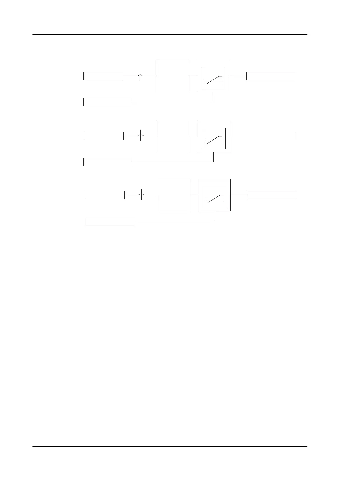
Figure 752: Functional module diagram
Level detector
This module compares the differential current I_A to the set
Start value
. The timer
module is activated if the differential current exceeds the value set in the
Start value
setting.
Timer
The time characteristic is according to DT. When the alarm timer reaches the value
set by
Alarm delay time
, the ALARM output is activated. If the fault disappears before
the module generates an alarm signal, the reset timer is activated. If the reset timer
reaches the value set by
Reset delay time
, the alarm timer resets. The activation of
the BLOCK signal resets the Timer and deactivates the ALARM output.
Lockout logic
HZCCxSPVC is provided with the possibility to activate a lockout for the ALARM
output depending on the
Alarm output mode
setting. In the "Lockout" mode, the
ALARM must be reset manually from the LHMI Clear menu after checking the CT
secondary circuit. In the "Non-latched" mode, the ALARM output functions normally,
that is, it resets as soon as the fault is cleared.
6.3.6 Measuring modes
The function operates on two alternative measurement modes, DFT and Peak-to-
Peak. The measurement mode is selected using the
Measurement mode
setting.
1MRS759142 F
Supervision functions
REX640
Technical Manual
1321

 Loading...


