EasyManua.ls Logo

ABB RELION REX640 - 9.10.5.1 Voltage and current measurements

ABB RELION REX640
1960 pages
To Next Page IconTo Next Page
To Previous Page IconTo Previous Page
Loading...
TCO
RSV
TAP_POS
LTC_BLOCK
Blocking
scheme
ALARM
Auto
parallel
(NRP)
t
Timer
t
Alarm
indication
Auto
parallel
(Follower)
Auto
single
Automatic
voltage
regulation
FLLW1_CTL
FLLW2_CTL
FLLW3_CTL
PAR_FAIL
Auto
parallel
(Master)
I3P1
I1_A
I1_B
I1_C
U3P1
U1_AB
Auto
parallel
(MCC)
TR3_DAT
TR1_DAT
TR2_DAT
Pulse
control
RAISE_OWN
LOWER_OWN
PARALLEL_IN
AUTO_IN
Operation
mode
selection
RAISE_LOCAL
LOWER_LOCAL
CON_STATUS
Parallel
manual
PARALLEL
AUTO
MSTR_TRIGG
FLLW4_CTL
FLLW5_CTL
TR4_DAT
TR5_DAT
BLKD_I_LOD
BLKD_U_UN
RNBK_U_OV
BLKD_I_CIR
BLKD_LTCBLK
TIMER_ON
MASTER
Manual
voltage
regulation
Manual
TAP_DIFF
Reverse
power flow
handling
REV_REG
I3P2
I2A
I2_B
I2_C
U3P2
U2_AB
PWR_DIR
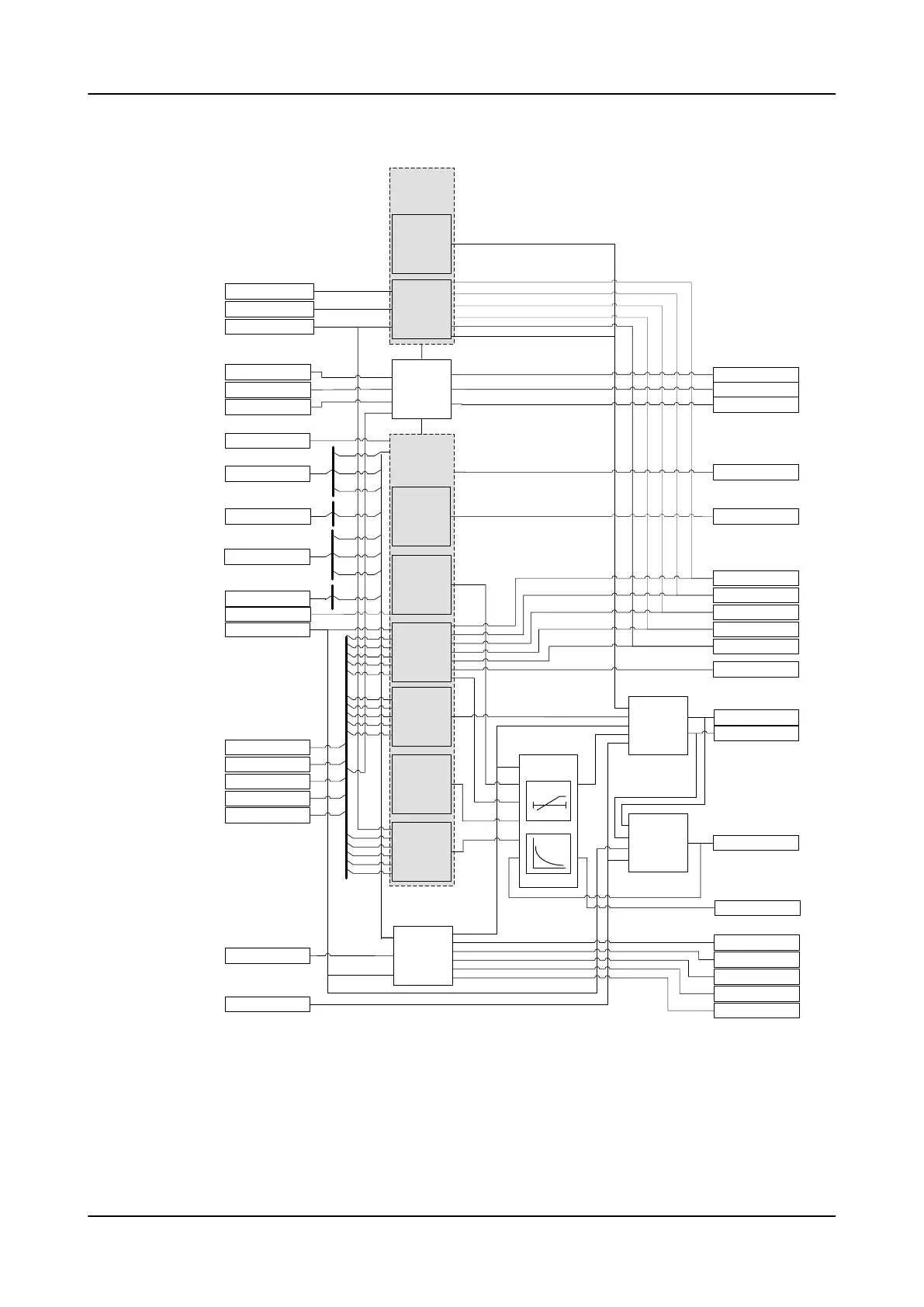
Figure 915: Functional module diagram
9.10.5.1 Voltage and current measurements
The measured voltage must be a phase-to-phase voltage from the regulated
side. Typically, it is the phase-to-phase voltage U_AB from the secondary side
1MRS759142 F
Control functions
REX640
Technical Manual
1697

Table of Contents

Other manuals for ABB RELION REX640

Related product manuals